00195376-05_SM_D1_D1i_D2_D2i_EN.pdf - 第241页
Settings 6.5.11 Performing a Vacuum Test on the C &P 6/12 DLM Heads Collec t&Place Head Service Manual SIPLACE D1/D1i/D2/D2i 241 Vacuum test with closed nozzle ► Start S ITEST and per form the first re ference ru…
Settings
Collect&Place Head 6.5.11 Performing a Vacuum Test on the C&P 6/12 DLM Heads
240 Service Manual SIPLACE D1/D1i/D2/D2i
Repeat these adjustments several times, as the pick - up / placement circuit are mutually dependent.
6.5.11
6.5.11 Performing a Vacuum Test on the C&P 6/12 DLM Heads
Performing a Vacuum Test on the C&P 6/12 DLM Heads
Damage to the valve plunger, silicone hose, the vacuum plate, in or on the nozzle can lead to leakage
which may then cause malfunctions during the placement process or which may reduce the vacuum val-
ue in the holding circuit.
Air Pressure Values Set with compressed air testing de-
vice
Measured at nozzle:
Displayed on the monitor:
(Only in pickup and placement
circuit)
pick - up / placement circuit 150 mbar (100 - 200 mbar) e.g.: 250 mbar
Reject circuit 250 mbar (200 - 300 mbar) Reject circuit does not have a
sensor
NOTICE
The two air blast circuits are controlled via a single valve and therefore influence one another
mutually. However, two different adjustment valves (see items 3 and 4 in the diagram above)
can be used to set the various pressures for each circuit.
NOTICE
Make sure the measurement sensor hose is fitted tightly on the nozzle.
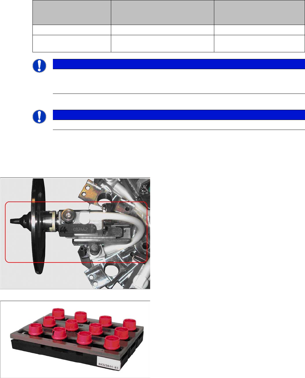
Vacuum test with normal nozzle configuration
▪ The vacuum tests for C&P6/12 in the station software
of the C&P12/6 placement heads only checks the
area from the vacuum generator to the valve plung-
ers.
▪ The area visible here (red frame), from the valve
plunger housing via the silicone hose into the seg-
ment housing and through the sleeve to the nozzle is
not covered by the normal vacuum test.
Equipment required
Closed nozzle tips are required for checking the complete
vacuum circuit.
The special nozzle use for this is marked red and does
not have a nozzle configuration on it:
▪ SOKO nozzle for vacuum test DLM, Item No.
[03067029-01]
Settings
6.5.11 Performing a Vacuum Test on the C&P 6/12 DLM Heads Collect&Place Head
Service Manual SIPLACE D1/D1i/D2/D2i 241
Vacuum test with closed nozzle
► Start SITEST and perform the first reference run, if
required.
► Select the gantry for the required vacuum test on the
C&P6/12 placement head.
► Place all the nozzles for the placement head in the
nozzle changer.
► Replace the full magazine at one magazine position
with the magazine holding the test nozzles
[03067029-01].
► Go to the Nozzle on head for segment 1 menu and
select the nozzle type which was originally configured
for this magazine position.
► Select the checkbox All segments as segment 1
► Pick up the vacuum test nozzles with all segments.
► Select the vacuum test menu and perform a vacuum
test.
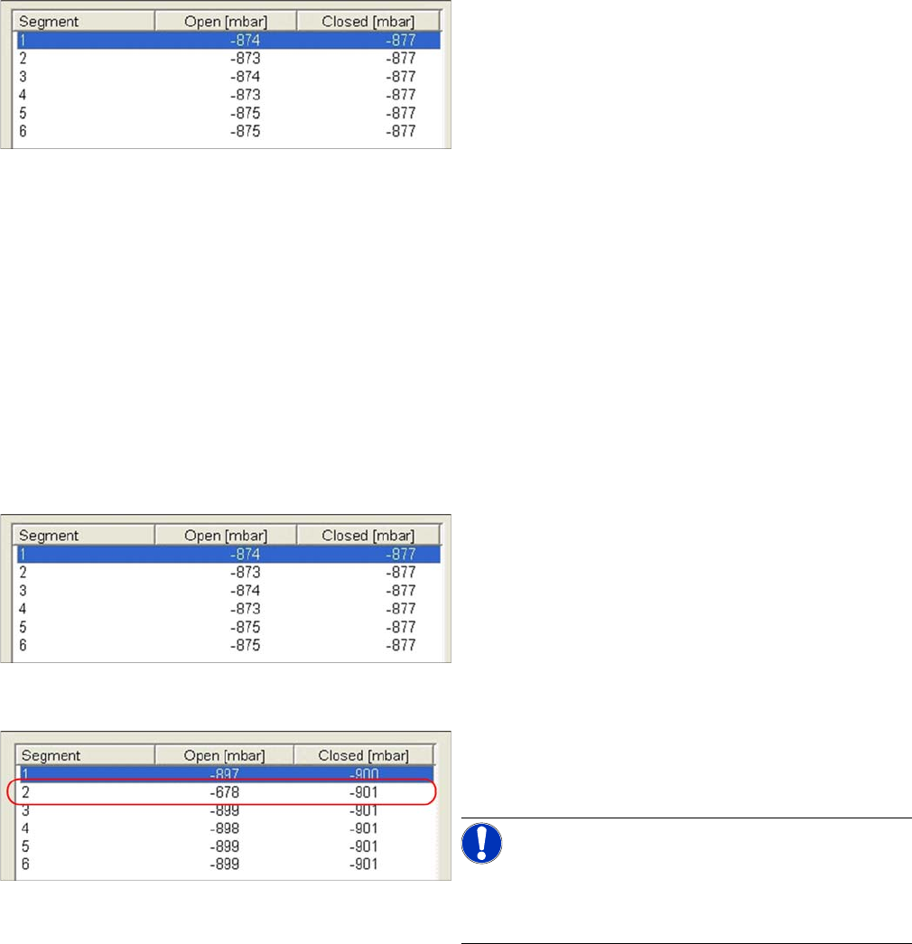
► The error message Vacuum difference open/closed
too low can be ignored here.
▪ As you can see in the measurement values here, the
Open values deviate by up to 3mbar from the Closed
values.
▪ However, this is within the tolerance of 5 mbar, in
which correct function can be reliably assumed.
► If this tolerance value is exceeded, check the valve
plunger and vacuum plate and replace these a a pre-
caution, if necessary.
Scenario 1
Example of faulty vacuum values, which indicate a dam-
aged vacuum plate at segment 2 here.
NOTICE! Irreparably damaged vacuum plate
If both measurements for a particular segment are
around 640mbar, this indicates that the vacuum plate is
irreparably damaged.
Settings
Collect&Place Head 6.5.12 Other Mechanical Settings on the Star
242 Service Manual SIPLACE D1/D1i/D2/D2i
Maintenance recommendations:
▪ Use the valve plunger ONLY when greased. (Isoflex topas).
▪ Replacing the valve plunger also means:
– Clean the valve plunger housing! Otherwise good plungers with new grease are installed in the
old, contaminated environment.
– Grease the valve plunger: Use the appropriate tool [03049689-01] to grease the valve plunger.
– Perform vacuum tests with the red SOKO nozzles, vacuum test DLM [03067029-01].
▪ Regularly check the sleeve-nozzle vacuum plate "blue" (available from 10/2008, white) and replace
when necessary (with 1.5mm Allen key).
6.5.12
6.5.12 Other Mechanical Settings on the Star
Other Mechanical Settings on the Star
▪ Set the air blast tube so that it overlaps the circular guide frame by 0.7 mm.
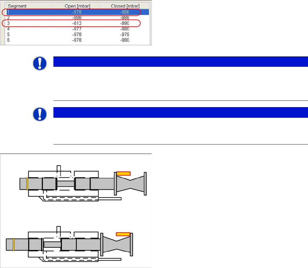
Scenario 2
Example of defective vacuum values, which indicate a
damaged silicone hose on segment 1 and an open nozzle
at segment 3.
NOTICE
Silicone hose defect
Under certain circumstances, silicone hose defects might only be detected when the segments
are moved out. It could therefore be advisable to release the Z axis and to perform a vacuum
test of the segment in its lowered state (single measurement run).
NOTICE
Missing valve plunger
If both measurements for a particular segment are only around 210mbar, this indicates that the
valve plunger is missing.
Vacuum values and valve plunger positions
▪ If the valve plunger is in the position "nozzle open",
the vacuum area will be sealed against the environ-
ment with two seals.
▪ If the valve plunger is in the position "nozzle closed",
the vacuum area (at the rear, near the drive) will be
sealed against the environment with only one seal.
If the "vacuum value closed" is too low, this indicates that
the seal is not sufficiently greased or that it is damaged.