00195376-05_SM_D1_D1i_D2_D2i_EN.pdf - 第225页
Settings 6.4.6 Star Axis Control System Axis Control Service Manual SIPLACE D1/D1i/D2/D2i 225 6.4.6 6 . 4 . 6 S t a r A x is C o n t r o l S y s t e m Star Axis Control System 6.4.6.1 6 . 4 . 6 . 1 C h e c k in g t h e S…
Settings
Axis Control 6.4.5 Track Signals for Head Axes
224 Service Manual SIPLACE D1/D1i/D2/D2i
See also
5.5 Track Signal Tester [00322510-01] [ ➙ 197]
6.4.5.3
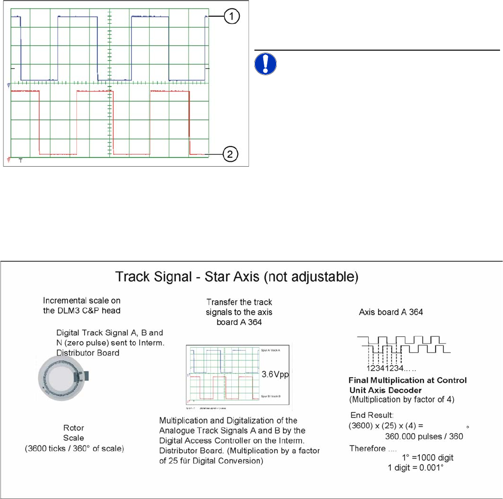
6.4.5.3 Preparing Track Signals for Star Axis Control (Example)
Preparing Track Signals for Star Axis Control (Example)
Digital head axis track signals
Legend
1. Track A
2. Track B
NOTICE! The pulse width is dependent on the
speed, the phase location is dependent on the direction.
Settings
6.4.6 Star Axis Control System Axis Control
Service Manual SIPLACE D1/D1i/D2/D2i 225
6.4.6
6.4.6 Star Axis Control System
Star Axis Control System
6.4.6.1
6.4.6.1 Checking the Star Axis Dynamics
Checking the Star Axis Dynamics
Measurement Setup
Signal Example with the Vnom. Output
The star axis dynamics are checked in the permanent star step mode. A motor phase current is emitted
at the V
nominal
output of the axis test box. (control signal 1). The uncommutated current setpoint signal
(signal 3) shows increased friction values for the axis.
The positioning time for the star axis is 43 +/-3 ms for the C&P12.
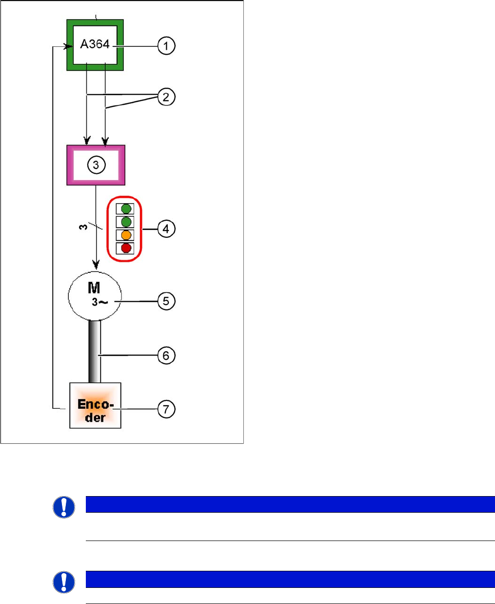
Star axis control system
The star axis is driven via a 3-phase AC stepping motor
with an intermediate circuit voltage of 150 V. The activa-
tion is via two control signals (phase shift 120°) from the
processor of the A364 I
target "W"
and I
target "U"
. The third
phase is calculated automatically.
Legend
1. Axis board A364
2. Control signals I
target
"W"
and I
target
"U"
3. Servo amplifier
4. LEDs on servo amplifier:
5. 3 phase AC motor.
6. Between the motor and the incremental encoder
there is a fixed mechanical connection.
7. Incremental encoder: transmits the exact position of
the axis. The track signals are the only feedback sig-
nals for the axes.
The servo board controls the motor directly.
NOTICE
Before adjusting the axes, make sure that the machine has reached its operating temperature.
Switch the machine on at least 30 minutes before you begin work.
NOTICE
The measurement procedure follows the same preparations and procedures as for the X axis.
Settings
Axis Control 6.4.6 Star Axis Control System
226 Service Manual SIPLACE D1/D1i/D2/D2i
SITEST:
► Select C&P heads ==> Select head ==> Axis functions
==> Select the star axis ==> Star continuous operation ==> Entry: waiting period 500 ms
==> Accept.
► Press the START button if required.
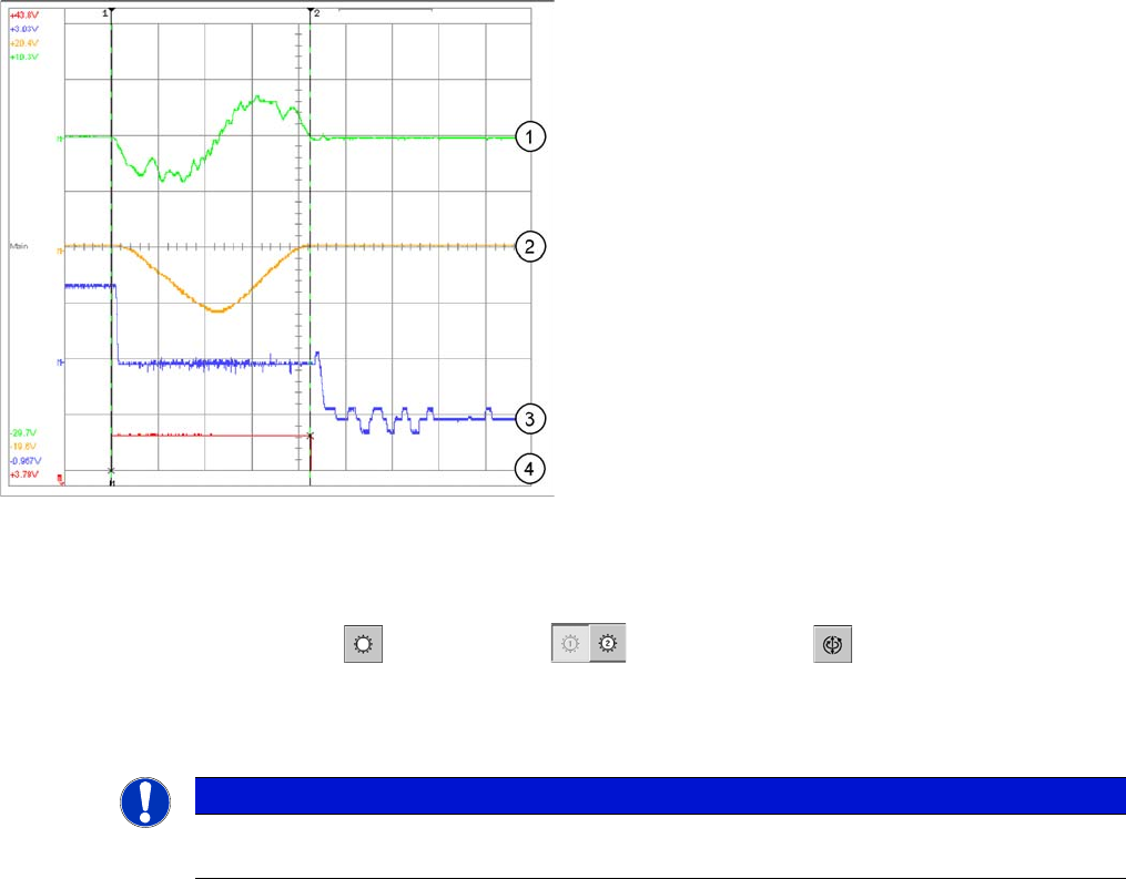
Dynamic signals and travel curves of star axis for C&P12
Legend
1. Current signal for axis adapter
2. Control signal (axis test box V nom.) Current target
value: 2V/Div
3. Deviation of position 500mV/Div
4. End signal
Time basis: 10ms/Div
Target positioning time: 43ms +/3ms
1 step = 30000 digits = 30 degrees
NOTICE
If the dynamics are significantly slower, check the friction blocks on the star and the installation
of the star in the drive's magnetic neutral position.