00195376-05_SM_D1_D1i_D2_D2i_EN.pdf - 第216页
Settings Track Signals and Zero Pulse 6.3.2 Checking the Track Signals 216 Service Manual SIPLACE D1/D1i/D2/D2i ► Voltages V/Division decrease up to 0.5 V/Div. ► Set the track signal teste r switch to "Measure"…
Settings
6.3.2 Checking the Track Signals Track Signals and Zero Pulse
Service Manual SIPLACE D1/D1i/D2/D2i 215
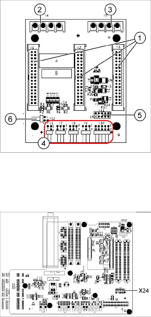
X11 on Y-axis gantry interface
X24 on X-Axis Gantry Head Distributor
6.3.2
6.3.2 Checking the Track Signals
Checking the Track Signals
6.3.2.1
6.3.2.1 Analog Track Signals
Analog Track Signals
► To check the track signals, connect the track signal tester and the oscilloscope. (See "6.3.1.1 Meas-
uring the Analog Zero Pulse Signal" [ ➙ 212].)
Oscilloscope settings: Connect CH1 to track A, CH2 to track B.
► Switch the machine on.
► Switch the track signal tester to Calibrate oscilloscope.
► Set both oscilloscope channels to GND. Place the lines for CH1 and CH2 over one another (on the
zero line of the coordinate system).
► Set both channels to DC, Refr., Non Store, Autotrigger (20 ms).
Legend
1. X1/X2/X3 flat ribbon cable
2. X4 motor Y-axis (U,V,W)
3. X5 motor X-axis (U,V,W)
4. X6 Temperature sensor X motor
X7 End position proximity switch Y axis (not used)
X8 Reference proximity switch Y axis (not used)
X9 Anticrash sensor (not used)
X10 connector for Y axis track signals
5. X11 test connector for Y-axis track signals
6. X12 Y-motor temperature sensor
Connector assignment X11
▪ Pin 1 Ground
▪ Pin 2 Track A
▪ Pin 3 Track A\ A\ mean inverted A
▪ Pin 4 Ground
▪ Pin 5 Track B
▪ Pin 6 Track B\
▪ Pin 7 +5V
▪ Pin 8 Track N
▪ Pin 9 Track N\
▪ Pin 10 Key
Connector assignment X24
▪ Pin 1 Ground
▪ Pin 2 Track A
▪ Pin 3 Track A\
▪ Pin 4 Ground
▪ Pin 5 Track B
▪ Pin 6 Track B\
▪ Pin 7 +5V
▪ Pin 8 Track N
▪ Pin 9 Track N\
▪ Pin 10 Key
Settings
Track Signals and Zero Pulse 6.3.2 Checking the Track Signals
216 Service Manual SIPLACE D1/D1i/D2/D2i
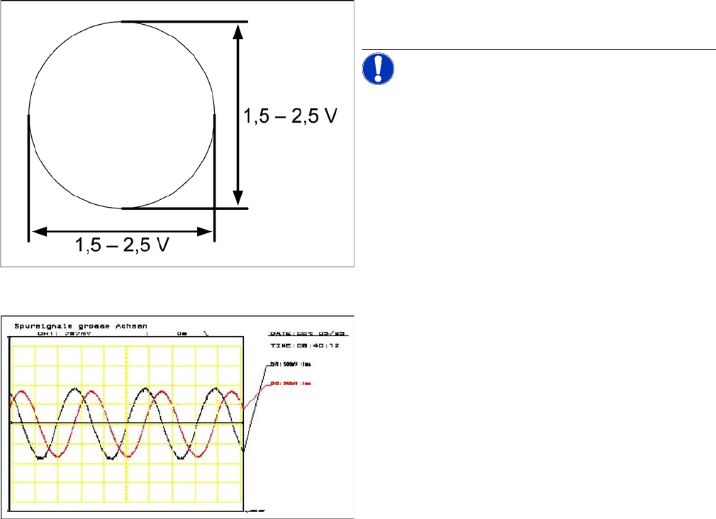
► Voltages V/Division decrease up to 0.5 V/Div.
► Set the track signal tester switch to "Measure".
► Switch the oscilloscope to X/Y --> Illuminated point will appear!
► Move the point into the middle of the display.
► Manually move the selected axis back and forth.
Analog track signals A and B in X/Y oscilloscope mode
► The adjacent picture should appear on the oscillo-
scope.
NOTICE! A new version of the incremental en-
coder (one field lens) can recognize signals from 1.8 to
3.6 Vss.
Analog track signals 90° phase shift
► Switch the oscilloscope from X/Y deflection to normal
mode.
► The adjacent picture should appear on the oscillo-
scope.
Settings
6.3.2 Checking the Track Signals Track Signals and Zero Pulse
Service Manual SIPLACE D1/D1i/D2/D2i 217
6.3.2.2
6.3.2.2 Digital Track Signals
Digital Track Signals
See also
6.3.1.2 Measuring the Digital Zero Pulse Signal [ ➙ 213]
6.3.2.1 Analog Track Signals [ ➙ 215]
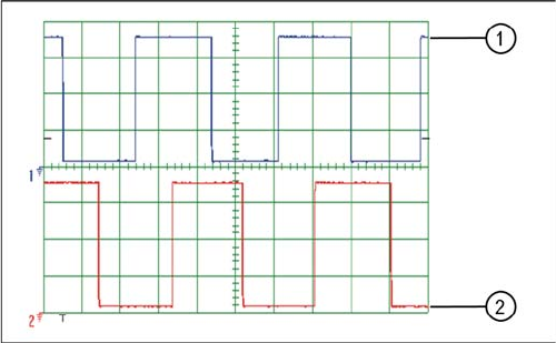
Digital track signals 90° phase shift
Legend
1. Track A
2. Track B
The digital track signals can only be measured at the Axis
Test Box.
Set both channels to 1 V / 20 ms. Note the 90 degrees
phase displacement.
The measurement structure for the axis test box is de-
scribed in section.