00195376-05_SM_D1_D1i_D2_D2i_EN.pdf - 第245页
Settings 6.6.2 DIP Switch for Camera Types 25, 33 and 36 Pick&Place Head Service Manual SIPLACE D1/D1i/D2/D2i 245 To (2) LEDs (description sequence downwards): ▪ D8 : Without functi on (return unit) ▪ D7 KLEMM : (Ret…
Settings
Pick&Place Head 6.6.1 Boards at P&P head
244 Service Manual SIPLACE D1/D1i/D2/D2i
6.6.1.1
6.6.1.1 P&P Head Main Board
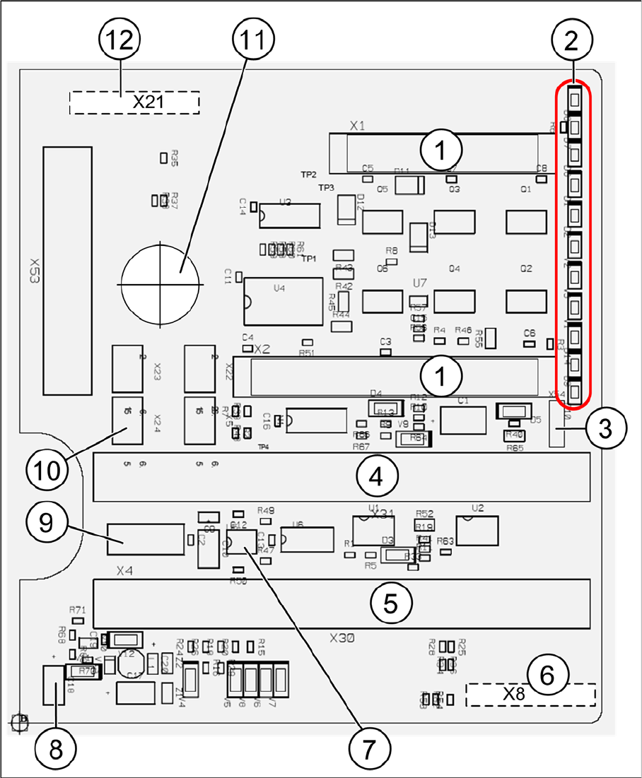
P&P Head Main Board
P&P head main board [00352833-xx]
Legend
The main board is mounted directly on the P&P head. This board is connected to the head adapter board
via two flat ribbon cables.

Settings
6.6.2 DIP Switch for Camera Types 25, 33 and 36 Pick&Place Head
Service Manual SIPLACE D1/D1i/D2/D2i 245
To (2) LEDs (description sequence downwards):
▪ D8: Without function (return unit)
▪ D7 KLEMM: (Return unit)
▪ D6 BERO: Z-axis top (not used)
▪ D1 DRUCK: Currently not used/ Z pressure
▪ D2 KLEMM: Clamping Z-axis (yellow) LED off, return unit is at top position
▪ V2 V_SP: Shows the 15 V voltage supply for the D axis track signals
The LEDs V2/V3 are OFF at jumper setting ON and old force measurement board. For Twin heads
with a new force measurement board, the 15 V will be controlled directly on the main board. This
means that the jumper must be OFF and the LEDs ON.
▪ V3 15V_: 15 V for the track signal D - axis currently OFF.
▪ V1 TEMP: Temperature monitoring Z-axis linear motor (red) LED OFF, is ok.
▪ D14 ALARM: Alarm output for the vacuum distributor (red LED ON vacuum distributor defective)
▪ D9 DRUCK: Currently not used/ Z pressure
▪ D10 24V+: Green LED ON 24V for the vacuum distributor
6.6.2
6.6.2 DIP Switch for Camera Types 25, 33 and 36
DIP Switch for Camera Types 25, 33 and 36
► Move the changeover table out of the machine.
► Switch off the machine.
► Remove the camera upper part and the cover on the lower part, to gain access to the DIP switches.
► Set the DIP switches. (See "6.6.2.1 Setting the Stationary Camera, Types 33, 36 and 25" [ ➙ 245].)
► Fit all parts by following the above instructions in the reverse order.
See also
4.5.7 Replacing the Stationary Digital Component/FC Camera [03020578-xx] [ ➙ 175]
6.6.2.1
6.6.2.1 Setting the Stationary Camera, Types 33, 36 and 25
Setting the Stationary Camera, Types 33, 36 and 25
An external Vision Control Unit is no longer required, as the camera base board (VLT33) is equipped
with its own controller (TQM).
1 2 connectors for the 16 bit CAN Bus processor
(not used)
7 EEPROM stores the head specific data (head
replacement, reference run)
2 LEDs (see below) 8 Power supply 15 V for the D axis track signals
(currently deactivated via the jumper X54)
3 X54 Jumper currently ON with the new force
measurement board set to OFF (see LED V2/
V_SP)
9 X4 Connector track signals Z axis
4 Connectors for flat ribbon cable of gantry head
distributor
10 Connector pneumatic valve (return unit)
5 Connectors for flat ribbon cable of gantry head
distributor
11 Hole for pneumatic pipe to the vacuum gener-
ator
6 X8: FleX Cable (Signals: D axis track signals,
power supply Z axis/D axis, Z temperature
and SPI bus)
12 X21 connector for vacuum generator

Settings
Pick&Place Head 6.6.2 DIP Switch for Camera Types 25, 33 and 36
246 Service Manual SIPLACE D1/D1i/D2/D2i
* Not all gantries may be available, depending on the machine type.
S Setting for gantry* Comments
1 2 3 4
1OF
F
OFF OF
F
OFF Bootstrap
2OF
F
OFF OF
F
OFF Reset
3OF
F
ON OF
F
ON Gantry ID 0
4OF
F
OFF ON ON Gantry ID 1
5OF
F
OFF OF
F
OFF Code 1
6OF
F
OFF OF
F
OFF CAN terminator
7ON ON ON ON CAN speed:ON:1 Mbit/s, OFF: 500 KB/s
8 xx xx xx xx x = OFF: FC camera (Type 25),
x = ON: IC camera (type 33, 36)