00195376-05_SM_D1_D1i_D2_D2i_EN.pdf - 第276页
Settings Changeover Table 6.7.13 LEDs on the TSP201 276 Service Manual SIPLACE D1/D1i/D2/D2i 6.7.12.3 6 . 7 . 1 2 . 3 S I E M E N S / S M E M A SIEMENS / SMEMA 6.7.12.4 6 . 7 . 1 2 . 4 S in g le / D u a l C o n v e y o r…
Settings
6.7.12 Jumper Settings for Conveyor Control TSP 201 Modular PCB Conveyor System
Service Manual SIPLACE D1/D1i/D2/D2i 275
6.7.12.1
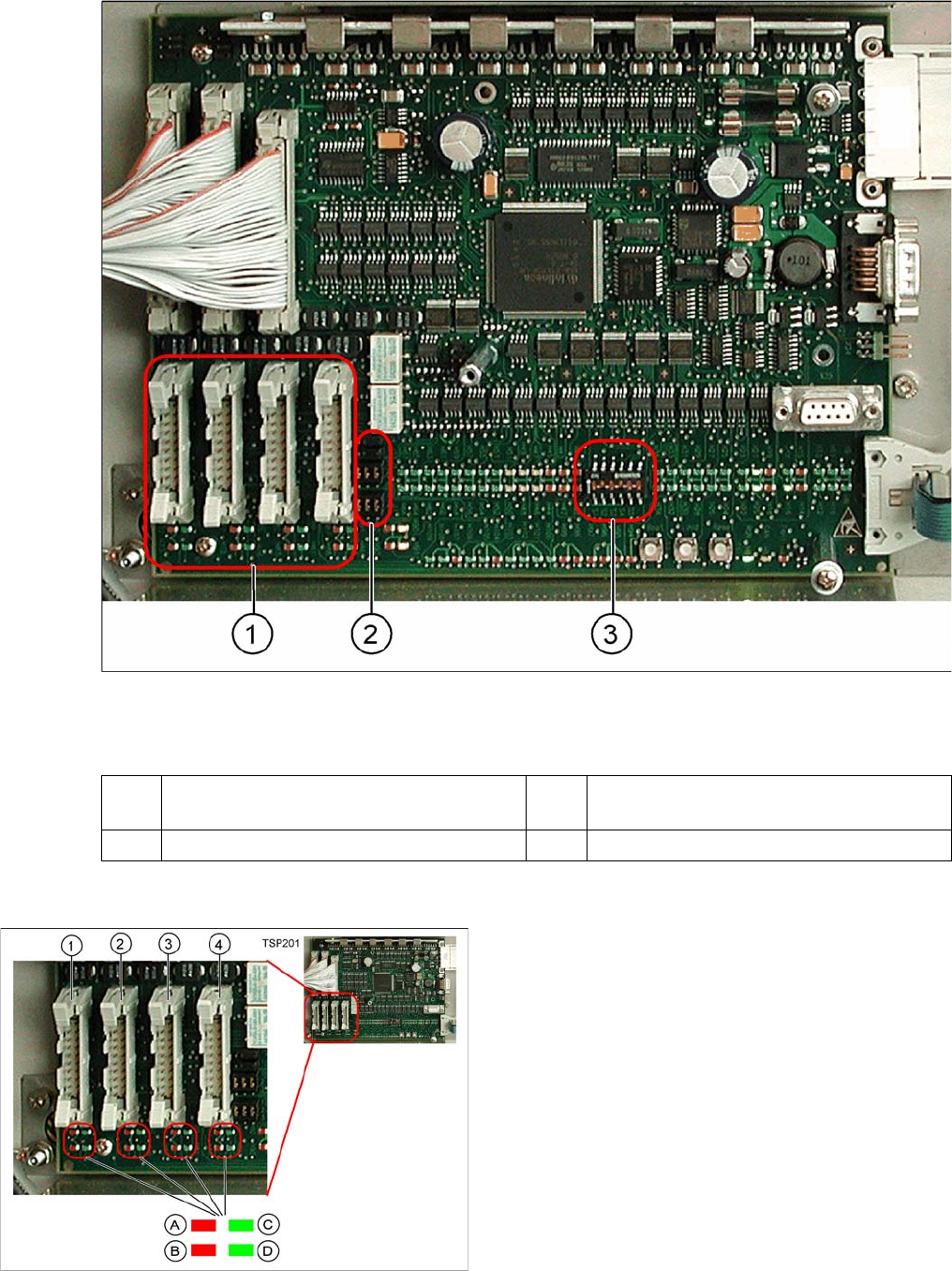
6.7.12.1 Overview
Overview
TSP 201
Legend
6.7.12.2
6.7.12.2 PCB Handling - Predecessor and Successor Station
PCB Handling - Predecessor and Successor Station
1 PCB handling (predecessor /successor
stations)
3 DIP switch for single / dual conveyors
2 Jumper for SIEMENS / SMEMA option
Legend
1. X1 – PCB handling – predecessor station lane 1
2. X2 – PCB handling – successor station lane 1
3. X4 – PCB handling – predecessor station lane 2
4. X5 – PCB handling – successor station lane 2
Connector and interface status display
▪ A = Received
▪ B = Permitted
▪ C = Transmitted
▪ D = Requested
Settings
Changeover Table 6.7.13 LEDs on the TSP201
276 Service Manual SIPLACE D1/D1i/D2/D2i
6.7.12.3
6.7.12.3 SIEMENS / SMEMA
SIEMENS / SMEMA
6.7.12.4
6.7.12.4 Single / Dual Conveyor
Single / Dual Conveyor
DIP switch S1 on TSP201
6.7.13
6.7.13 LEDs on the TSP201
LEDs on the TSP201
See also
6.2.3.1.2 Description of LEDs on the Gantry Head Distributor [ ➙ 209]
6.7.14
6.7.14 Siemens/SMEMA TSP 201 Interface Description
Siemens/SMEMA TSP 201 Interface Description
6.8
6.8 Changeover Table
Changeover Table
6.8.1
6.8.1 Setting the COT Basic Height
Setting the COT Basic Height
6.8.1.1
6.8.1.1 Tools and equipment
Tools and equipment
The following tools and equipment are needed to adjust the height of the component trolley:
▪ Set of Allen keys, size 5
▪ Eyebolt with M12 thread to raise the component trolley table,
DIN 580 M12-St [00048350-xx]
▪ Leverage device for raising the component trolley table, must be able to carry at least 80 kg
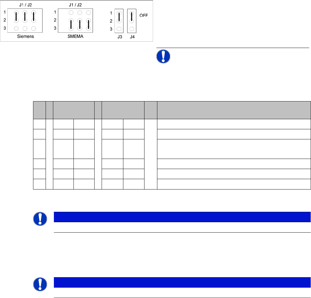
Jumper J1, J2 "successor/predecessor station" at TSP
201
Legend
▪ J1 predecessor station
▪ J2 successor station
▪ J3/J4 interference loop (emergency stop on produc-
tivity lift switches the placement machine off)
NOTICE! Jumpers J1 and J2 can be set inde-
pendently of one another, at SIEMENS or SMEMA.
S Single con-
veyor
Dual conveyor Comments
1OFF ON OFF = single conveyor, ON = dual conveyor
2ON ONStation type (always ON)
3OFF OFF OFF = clamping sensor disabled (with adj unit)
ON = without adj unit
4ON ONOFF = 125 Kbit/s (S27), ON = 1 Mbit/s (D1/D1i/D2)/D2i
5oo oo CAN terminating resistor, OFF for D1/D1i, ON for D2/D2i
6OFF OFF not used
NOTICE
See also the label on the TSP201 cover.
NOTICE
See also the label on the TSP201 cover.
Settings
6.8.1 Setting the COT Basic Height Changeover Table
Service Manual SIPLACE D1/D1i/D2/D2i 277
6.8.1.2
6.8.1.2 Adjusting the Component Trolley to the Board Transport Height
Adjusting the Component Trolley to the Board Transport Height
6.8.1.3
6.8.1.3 Adjusting the Component Trolley Height
Adjusting the Component Trolley Height
► Screw the eyebolt into the M12 hole provided (1) on the component trolley table.
► Hook the leverage device into the eyebolt (2).
► Tighten the rope of the leverage device.
► Loosen the 8 hexagon socket-head screws, M6x12 (4).
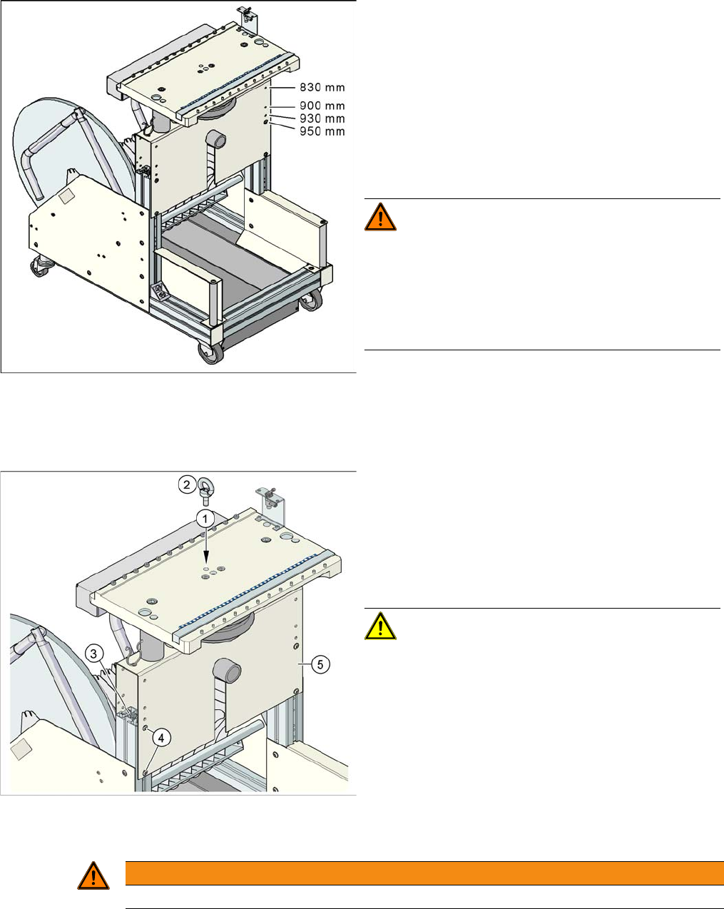
Component trolley with a PCB conveyor height of
950 mm (on example of D4)
Legend
▪ Holes drilled for board transport heights 830 -
950 mm in the guidance bars
The component trolley for the S feeder modules can be
easily and quickly adjusted to the following board trans-
port heights:
830 mm ±15 mm standard height
900 mm ±15 mm SMEMA height
930 mm ±15 mm SMEMA height
950 mm ±15 mm SMEMA height
WARNING! The component trolley height may
only be set by SIEMENS technicians or other qualified
and officially authorized (certified) personnel.
Observe the applicable accident prevention regulations.
Remove all feeder modules from the changeover table
plate, before you adjust the height of the changeover ta-
ble.
Position of eyebolt on component trolley (on example of
D4)
Legend
1. M12 hole drilled for eyebolt
2. Eyebolt DIN 580 M12-St
3. Vertical profile bar
4. 8 x hexagon socket-head screw SN 62355, M6x12
5. Bridge
CAUTION! Always use the fit-up aid (screwed
eyelet) to fix the table plate, irrespective of whether you
want to raise or lower the component trolley.
WARNING
Lift all feeder modules off the component trolley table plate.