User Manual SIPLACE Linear Dipping Unit 2 X.pdf - 第18页
2 Operational safety 2.6 IMDA Registration 18 User Manual SIPLACE Linear Dipping Unit 2 X 05/2020 2.5.3 FCC label on the LDU 2 X 1. The FCC label(1) is located on the right side of the LDU2X housing. 2.6 IMDA Registra…
2 Operational safety
2.5 FCC, RFID
User Manual SIPLACE Linear Dipping Unit 2 X 05/2020 17
► If the packaging is not conductive, place the modules in a conductive envelope before pack-
aging. Use conductive expanded rubber, ESD bags, domestic aluminum foil or paper, for
example. NEVER use plastic bags or film.
► If the module has integral batteries, ensure that the conductive packaging does not touch or
short circuit the battery terminals and, if necessary, first cover the terminals with insulating
tape or material.
2.5 FCC, RFID
2.5.1 FCC Caution
Any changes or modifications not expressly approved by the party responsible for compliance
could void the user's authority to operate this equipment. This device complies with Part 15 of the
FCC Rules. Operation is subject to the following two conditions:
1. This device may not cause harmful interference, and
2. This device must accept any interference received, including interference that may cause un-
desired operation.
NOTICE
This equipment has been tested and found to comply with the limits for a Class B digital
device, pursuant to part 15 of the FCC Rules. These limits are designed to provide reason-
able protection against harmful interference in a residential installation. This equipment
generates, uses and can radiate radio frequency energy and, if not installed and used in
accordance with the instructions, may cause harmful interference to radio communications.
However, there is no guarantee that interference will not occur in a particular installation. If
this equipment does cause harmful interference to radio or television reception, which can
be determined by turning the equipment off and on, the user is encouraged to try to correct
the interference by one or more of the following measures:
► Reorient or relocate the receiving antenna.
► Increase the separation between the equipment and receiver.
► Connect the equipment into an outlet on a circuit different from that to which the recei-
ver is connected.
► Consult the dealer or an experienced radio/TV technician for help.
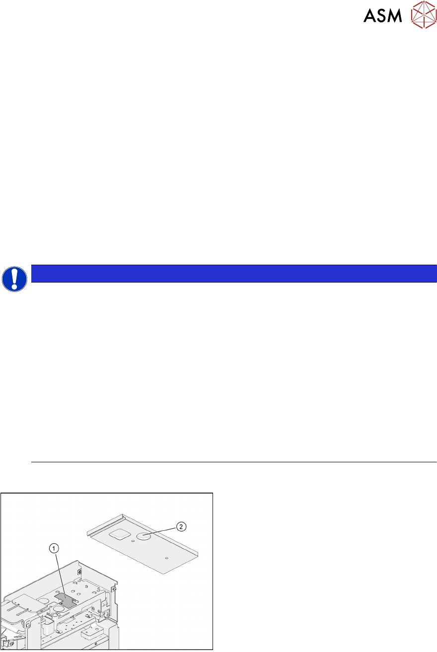
2.5.2 RFID on the LDU 2 X
1. The RFID module (1) is located on the top
side of the dip stroke plate.
2. The RFID transponder (2) is located on the
bottom side of the dipping plate.
2 Operational safety
2.6 IMDA Registration
18 User Manual SIPLACE Linear Dipping Unit 2 X 05/2020
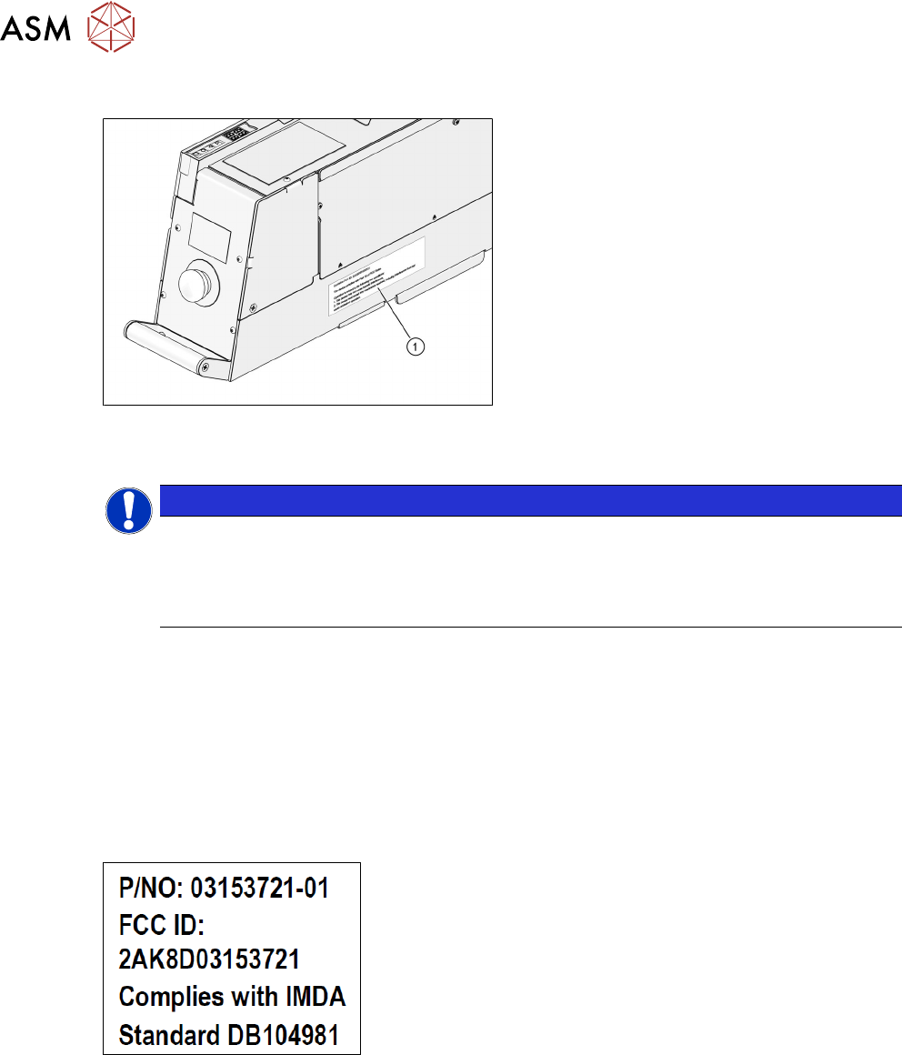
2.5.3 FCC label on the LDU 2 X
1. The FCC label(1) is located on the right
side of the LDU2X housing.
2.6 IMDA Registration
NOTICE
The equipment listed below has been registered with the Infocommunications Media Devel-
opment Authority under regulation 20(6) of the Telecommunications (Dealers) Regulations
(Cap 323, Rg 6) (the "Dealers Regulations") and approved for sale in Singapore. Your at-
tention is drawn to the relevant provisions and requirements of the Dealers described
below.
Declared Equipment Information
Brand/Trade Name: ASM
Model Name/No.: SIPLACE LDU 2 X
(c/w RFID Module 03153721‑01)
Equipment Description Linear Dipping Unit 2 X
2.6.1 IMDA label on the LDU 2 X
The SIPLACE Linear Dipping Unit 2 X complies with IMDA standards:
3 Function description and structure
3.1 Function description
User Manual SIPLACE Linear Dipping Unit 2 X 05/2020 19
3 Function description and structure
3.1 Function description
The LDU is set up on a changeover table in the same way as any other feeder module. The line
software (SIPLACE Pro) can be used to select components for dipping and to set the relevant
parameters. The LDU makes the flux available in a certain area, in the pre-defined amount (layer
thickness). The layer of flux is always renewed by automatically performed application runs. This
ensures that the components are dipped in a fresh layer of flux and that consistent process condi-
tions are maintained.
The LDU can be roughly divided into a mechanical section — an application unit — and an elec-
trical section — the so-called control unit.
Control unit
The control unit contains the electrical parts, such as the power supply, interfaces, the control sys-
tem and the operating unit.
Application unit
The application unit has two movement axes. The squeegee axis moves a slide unit back and forth.
The lifting axis moves the lifting unit up and down. Both of these axes are driven by electrical mo-
tors and a spindle system. A rotary encoder on the motor shaft determines the current position of
the spindle. Both axes have sensors which indicate when the axis reaches its end position.
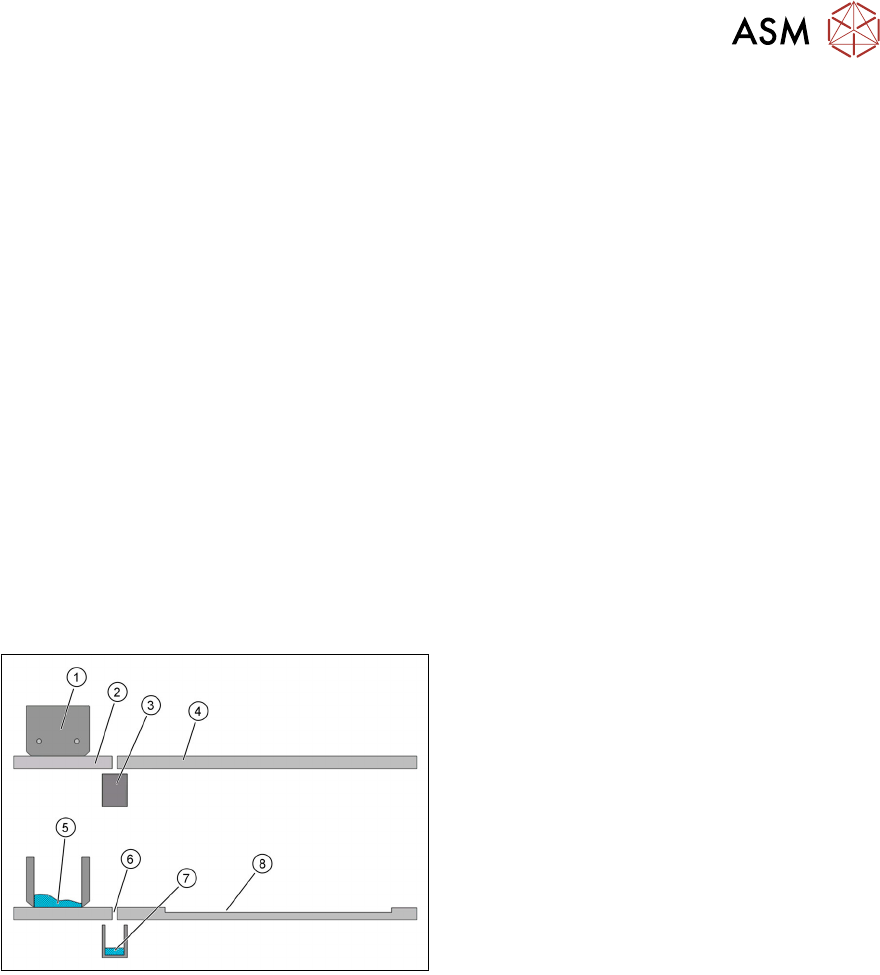
The application unit of the LDU consists of the
following main parts:
1. Flux tank
2. Park plate
3. Drip tray
4. Dipping plate
5. Flux
6. Interface
7. Flux in the drip tray
8. Cavity