User Manual SIPLACE Linear Dipping Unit 2 X.pdf - 第28页
3 Function description and structure 3.2 Structure 28 User Manual SIPLACE Linear Dipping Unit 2 X 05/2020 Dipping plate bottom side: 1. Dipping plate 2. Cavity plate 3. Stop plates The Auto Cavity dipping plate allows fo…
3 Function description and structure
3.2 Structure
User Manual SIPLACE Linear Dipping Unit 2 X 05/2020 27
The following dipping plates with RFID transponder are available for the LDU 2 X:
Item number Depth of cavity [µm] Item number Depth of cavity [µm]
03168214-xx 10 03168286-xx 190
03168210-xx 15 03168287-xx 200
03168206-xx 20 03168288-xx 210
03168202-xx 25 03168289-xx 220
03168198-xx 30 03168290-xx 230
03168196-xx 35 03168291-xx 240
03168191-xx 40 03168292-xx 250
03168194-xx 45 03168293-xx 260
03168185-xx 50 03168294-xx 270
03168181-xx 60 03168295-xx 280
03167724-xx 70 03168296-xx 290
03168275-xx 80 03168297-xx 300
03168276-xx 90 03168298-xx 310
03168277-xx 100 03168299-xx 320
03168278-xx 110 03168300-xx 330
03168279-xx 120 03168301-xx 340
03168280-xx 130 03168302-xx 350
03168281-xx 140 03168303-xx 360
03168282-xx 150 03168304-xx 370
03168283-xx 160 03168305-xx 380
03168284-xx 170 03168306-xx 390
03168285-xx 180 03168307-xx 400
Dipping plate with adjustable cavity depth (only for LDU 2 X with Auto Cavity
option)
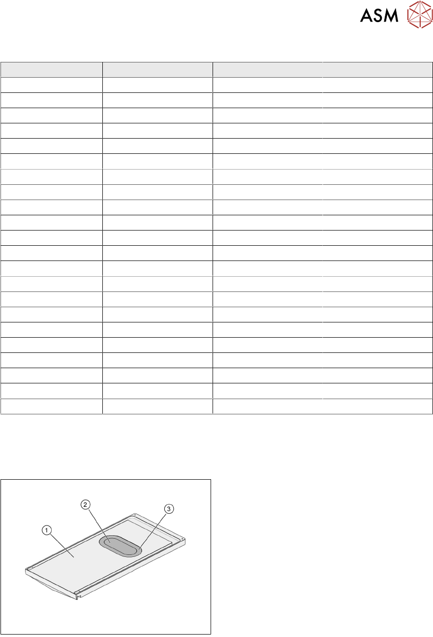
The adjustable cavity of the Auto Cavity dipping plate consists of a movable cavity plate, which is
connected to the dipping plate body by a flexible seal.
Dipping plate top side:
1. Dipping plate
2. Cavity plate
3. Seal
On the bottom side of the dipping plate, the cavity plate is supported by two stop plates, which
define the lowest position of the cavity plate and also ensure mechanical stability during the dipping
process.
3 Function description and structure
3.2 Structure
28 User Manual SIPLACE Linear Dipping Unit 2 X 05/2020
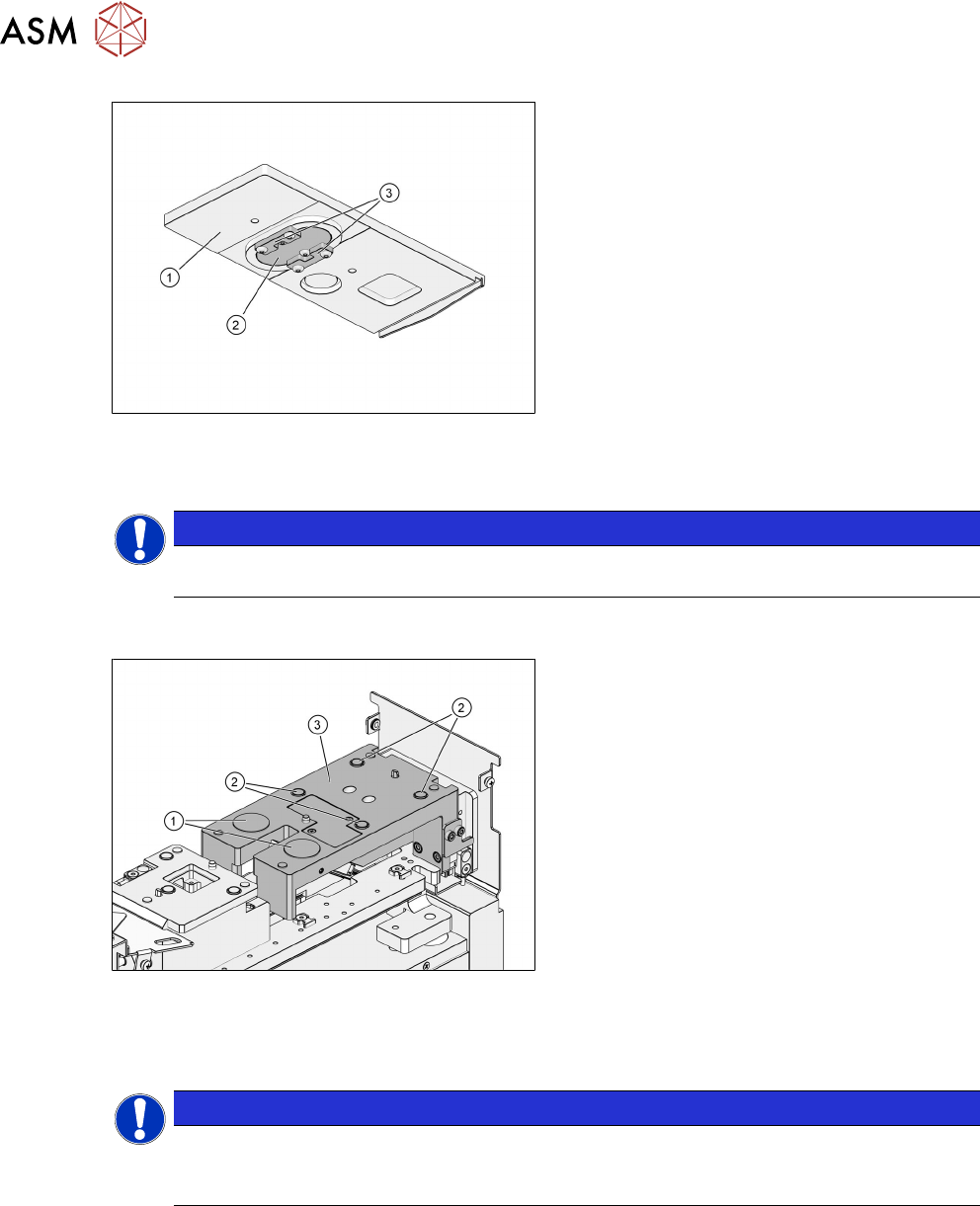
Dipping plate bottom side:
1. Dipping plate
2. Cavity plate
3. Stop plates
The Auto Cavity dipping plate allows for cavity depths from 0.01mm to 0.25mm with an adjust-
ment tolerance of ±10 µm. The maximum component size that can be used on this dipping plate is
15 mm x 25 mm.
NOTICE
All existing standard dipping plates with fixed cavity depths can also be used with the
LDU2X with Auto Cavity option.
3.2.6 Dip stroke plate
1. Electromagnets
2. Permanent magnets
3. Dip stroke plate
The dipping plate is held in place on the by four permanent magnets. Two electromagnets are used
for additional fixing dip stroke plate and check whether a dipping plate is fitted. The electromagnets
detect changes in the distance between dipping plate and dip stroke plate. This will be the case
when the dipping plate gets stuck to the park plate during the downwards movement.
NOTICE
Dipping plate not available
If the dipping plate does not fit properly, the dipping plate is not recognized and "plate not
available" is displayed.
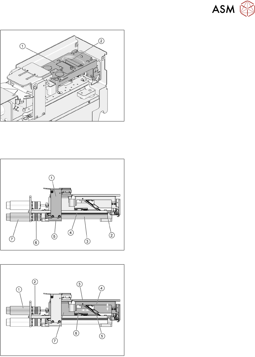
Dip stroke plate for LDU 2 X with Auto Cavity option
The dip stroke plate of the LDU 2 X with Auto Cavity option is a special design with a height adjust-
ment mechanism. A vertically movable pusher block contacts the cavity plate and controls its ver-
tical position.
3 Function description and structure
3.2 Structure
User Manual SIPLACE Linear Dipping Unit 2 X 05/2020 29
1. Dip stroke plate
2. Pusher block
3.2.7 Axes
The LDU has two drive axes.
The squeegee axis moves the squeegee forwards and backwards.
1. Squeegee
2. Front bearing block
3. Spindle
4. Guide rail
5. Rear bearing block
6. Coupling
7. Motor
The lifting axis moves the dipping plate up and down:
1. Motor
2. Coupling
3. Dipping plate
4. Dip stroke plate
5. Guidance
6. Slide
7. Bearing block (base of park plate)
The maximum lift of the lifting axis is -8.5mm to +22mm (mechanical stoppers). The basic position
(determined by an inductive switch) is at -7.5mm. The squeegee is positioned at 0mm. The dip-
ping position is at +17.5mm. Squeegee and dipping position are determined by the pulse gener-
ator of the motor.