User Manual SIPLACE Linear Dipping Unit 2 X.pdf - 第62页
4 Operation 4.5 Checking the layer thickness 62 User Manual SIPLACE Linear Dipping Unit 2 X 05/2020 ► Measure the cavity depth with the gauge. If the measured value does not match the reference value teach the auto cavit…
4 Operation
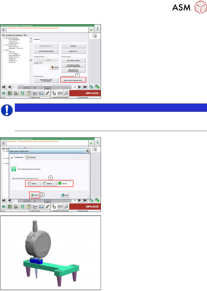
4.4 Adjust cavity depth
User Manual SIPLACE Linear Dipping Unit 2 X 05/2020 61
► Click on the Adjust cavity of dipping
plate… button (1).
NOTICE
Notice
The Adjust cavity of dipping plate… button is only displayed if a corresponding dipping
plate is available.
► Choose 50 µm, 100 µm or 150 µm as ref-
erence value (1)
.
► Click the Start button (2).
ð The auto cavity dipping plate moves to
the selected reference value.
► Install the mechanical gauge (measuring
device LDU HA [03118995-xx]).
4 Operation
4.5 Checking the layer thickness
62 User Manual SIPLACE Linear Dipping Unit 2 X 05/2020
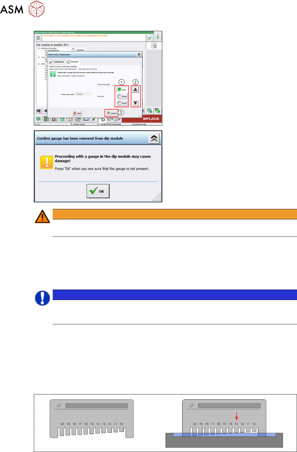
► Measure the cavity depth with the gauge. If
the measured value does not match the
reference value teach the auto cavity plate
to the set value (50/100/150 µm) in steps.
► Choose the step size 2/10/50 µm (1) and
correct the measured value step by step
by clicking the Upward
or Downward but-
ton (2)
until the reference value is reached.
► Click the Accept button (3) to save the off-
set of the auto cavity dipping plate and the
LDU.
► Remove the gauge from the dip module.
The request must only be confirmed by
clicking OK
if you are sure that the gauge
has really been removed!
WARNING
Danger of damage
Proceeding with a gauge in the dip module may cause damage!
The LDU saves the determined offset together with the serial number of the dipping plate internally.
The LDU saves the offset values for a maximum of 10 different auto cavity dipping plates. Saving
an additional dipping plate will delete the data of the oldest dipping plate.
4.5 Checking the layer thickness
NOTICE
Target group: setup operator
The procedure described is a task that occurs irregularly and should only be carried out by
a trained operator with special knowledge (setup operator).
There are numerous measuring devices for paintshops and coating specialists on the market,
which are used to measure the layer thicknesses of paints, varnishes, pastes etc.
(wet film thickness measurement gauge). Two common means of measuring are explained below.
One of the main advantages of these instruments is their ease of use. Precise measurements are
achieved quickly in the production environment.
4.5.1 Layer thickness measurement "comb"
Structure of measuring device
4 Operation
4.5 Checking the layer thickness
User Manual SIPLACE Linear Dipping Unit 2 X 05/2020 63
On one side of the rectangular measuring instrument there are engraved teeth with increasing spa-
cing from the contact surface. A scale is marked above the teeth and the engraved numbers indic-
ate the distance from the contact surface in µm. These measuring devices are usually made of
steel so that they can be cleaned with solvents.
Measurement principle
The measuring device is dipped into the layer of flux. The point at which the flux touches a tooth is
the layer thickness measurement (arrow in right-hand image).
Performing the measurement
► Place the measuring device onto the flux surface as shown above and press down to the base
of the cavity.
► Perform a brief "combing" movement while applying moderate pressure.
► Take the measuring device vertically up and out of the flux.
► Determine the shortest tooth which is coated by flux.
► Read the value on the scale at this point.
4.5.2 Layer thickness measurement "roller"
Structure of measuring device
The measuring device consists of a rotating handle and three rollers. The innermost roller has a
small diameter and runs eccentrically to the other two outer rollers. A scale is marked on the out-
side. These measuring devices are usually made of stainless steel so that they can be cleaned with
solvents.
Measurement principle
The measuring device is rolled through the layer of flux. The two outer rollers moved on the base of
the cavity. The eccentrically aligned middle roller is rotated and guided towards the surface of the
flux. The point at which the flux touches this middle roller is the layer thickness measurement.