User Manual SIPLACE Linear Dipping Unit 2 X.pdf - 第48页
4 Operation 4.1 Settings in SIPLACE Pro 48 User Manual SIPLACE Linear Dipping Unit 2 X 05/2020 4.1.4 Selecting a component for dipping For every component used, the user can set that dipping is required: ► In SIPLACE Pro…

4 Operation
4.1 Settings in SIPLACE Pro
User Manual SIPLACE Linear Dipping Unit 2 X 05/2020 47
Assigning a flux to the LDU 2 X
► Click on the blank field in the Processing Material column of the Dipping Division Paramet-
ers area(1).
A Select button with three points is displayed.
► Click on the Select button(2).
A dialog window is displayed.
► Click on the desired flux material in the tree view(3).
► Click OK(4).
The dipping plate and the flux assigned to the LDU 2 X are now displayed in the Dipping Division
Parameters table in the Feeders area(1) and on the LDU 2 X symbol in the display area(2).
4 Operation
4.1 Settings in SIPLACE Pro
48 User Manual SIPLACE Linear Dipping Unit 2 X 05/2020
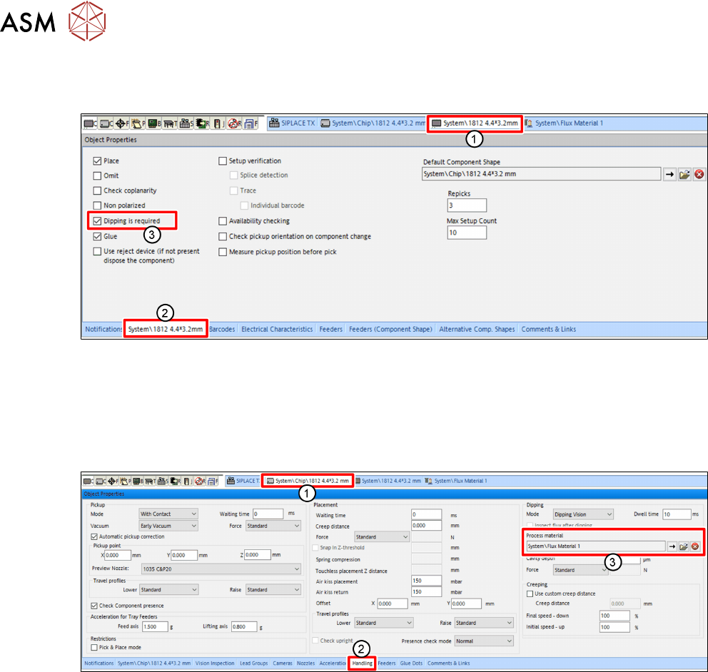
4.1.4 Selecting a component for dipping
For every component used, the user can set that dipping is required:
► In SIPLACE Pro, click on the tab of the desired component(1).
► Click on the tab of the component(2) in the Object Properties view.
► Enable the Dipping is required option(3).
4.1.5 Assigning a flux to a component
The user must assign a flux to a component for which dipping is required.
► In SIPLACE Pro, click on the tab of the component shape of the desired component(1).
► Click on the Handling tab(2) in the Object Properties view.
► Click on the button with the arrow next to Process Material(3) in the Dipping area.
A dialog window is displayed to select the flux.
► Click on the desired flux in the tree view.
► Click on OK.
4 Operation
4.1 Settings in SIPLACE Pro
User Manual SIPLACE Linear Dipping Unit 2 X 05/2020 49
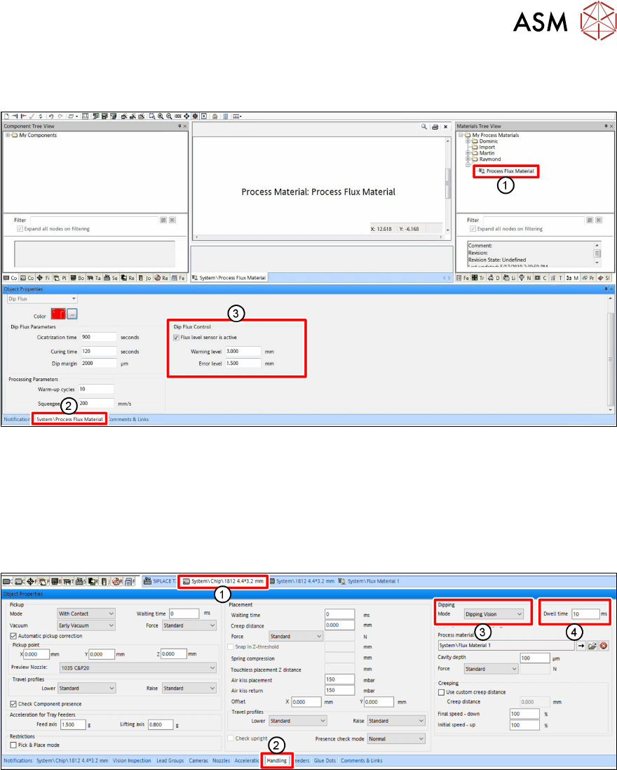
4.1.6 Setting the Flux Level Sensor parameters
The parameters for the Flux Level Sensor are flux-specific:
► In SIPLACE Pro, select the flux material (1) from the Materials Tree View.
► Click on the tab of the flux material (2) to display its properties in the editor.
► In the Dip Flux Control area (3), mark Flux level sensor is active to activate the flux level
sensor for this particular flux material.
► Enter the appropriate values for the Warning level and the Error level.
4.1.7 Setting the dipping sequence and the dwell time
► In SIPLACE Pro, click on the tab of the component shape of the desired component(1).
► Click on the Handling tab(2) in the Object Properties view.
► Select the dipping sequence under Mode(3) in the Dipping area.
► Enter the dwell time in milliseconds[ms] in the Dwell time field (4).
For more information on the dwell time, see chapter 3.3.6 "Dipping process and dwell time" [}38].
For more information on the different dipping sequences, see the online help of the line software.