User Manual SIPLACE Linear Dipping Unit 2 X.pdf - 第24页
3 Function description and structure 3.2 Structure 24 User Manual SIPLACE Linear Dipping Unit 2 X 05/2020 1. Park plate 2. Flux Level Sensor 3. Front wall of the flux tank 4. Flux 5. Rear wall of the flux tank When the f…
3 Function description and structure
3.2 Structure
User Manual SIPLACE Linear Dipping Unit 2 X 05/2020 23
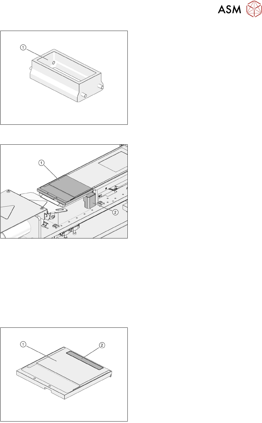
1. Flux tank for Auto Cavity dipping plate
3.2.3 Park plate and drip tray
1. Park plate
2. Drip tray
The park plate is held in place by permanent magnets. The shape of the drip tray is asymmetric so
that it cannot be fitted wrongly. Two sensors on the base determine whether a park plate or a drip
tray is fitted.
3.2.4 Flux Level Sensor
During production, the amount of flux in the flux tank decreases. If the amount of flux is too low to
fill the cavity in the plate, components can no longer be coated with flux to the quality required. To
avoid this, the amount of flux in the flux tank can be monitored by the Flux Level Sensor.
The Flux Level Sensor of the LDU 2 X is based on a capacitive structure, which generates an elec-
trical field. The capacitive structure is part of the top side layout of a PCB integrated in the park
plate.
1. Park plate
2. Flux Level Sensor
The capacitance of the Flux Level Sensor is affected by the permittivity of the flux or by any other
capacitive structure like the flux tank. When moving the flux tank, the flux forms a wave inside the
flux tank.
3 Function description and structure
3.2 Structure
24 User Manual SIPLACE Linear Dipping Unit 2 X 05/2020
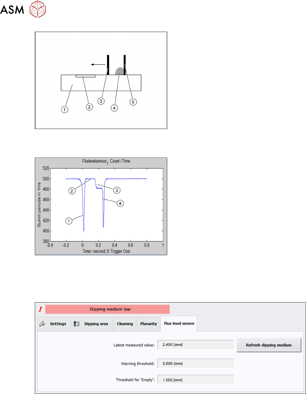
1. Park plate
2. Flux Level Sensor
3. Front wall of the flux tank
4. Flux
5. Rear wall of the flux tank
When the flux tank crosses the Flux Level Sensor, the front wall of the flux tank is followed by a
gap, then by the flux, and at last by the rear wall of the flux tank. Each capacitive structure evokes
a characteristic signal at the flux level sensor.
Capacitance signals of:
1. Front wall of the flux tank
2. Gap between wall and flux
3. Wave of the flux
4. Rear wall of the flux tank
The width of the wave of the flux [in millimeters] is a measure for the amount of flux inside the tank.
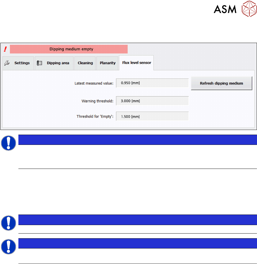
Two thresholds can be assigned to every particular flux material: Warning level and error level.
Both values depend on the type of flux material and need to be determined empirically.
If the amount of flux falls below the Warning level, the station software displays a corresponding
status message:
3 Function description and structure
3.2 Structure
User Manual SIPLACE Linear Dipping Unit 2 X 05/2020 25
If the amount of flux reaches the Error level, the station software displays a corresponding status
message:
NOTICE
Station software filters the measured values
Because the station software filters the measured values, the machine is not stopped if the
threshold is only exceeded briefly
Additionally, the station software also displays the warning message 31865 Dip Module: medium
empty. In this case, the LDU will be locked and components to be dipped will not be dipped and
placed.
See chapter 4.1.6 "Setting the Flux Level Sensor parameters" [}49] for how to operate the Flux
Level Sensor.
NOTICE
The LDU can also be operated with a park plate that does not have a Flux Level Sensor.
NOTICE
The Flux Level Sensor must be calibrated after an exchange of the park plate or the flux
tank. Please refer to the LDU 2 X service manual.