00195346-0302_SM_WPC4_EN.pdf - 第15页
Replacing Spare Parts Safety Instructions Service Manual SIPLACE WPC4 15 3 Replacing S p are Part s 3.1 Safety Instructions Preparations for service work X Finish all placement operations at the SIPLACE mach ine. X Switc…
Operational Safety
Safety Instructions ESD Guidelines
14 Service Manual SIPLACE WPC4
2.2.8 ESD Guidelines
2.2.8.1 Handling ESD Modules
Do not touch electronic modules unless it is absolutely essential to do so in order to carry out other work.
If it is necessary, make sure that you do not touch the pins or printed conductors when you pick up flat
modules.
Do not touch components unless
you are constantly earthed by an ESD wrist strap or
you are wearing ESD shoes or ESD shoe earthing strips on an ESD floor.
Always discharge yourself before you touch an electronic module. To do this, simply touch a conductive
and earthed object immediately before you touch the module (such as unpainted parts of a switch
cabinet, a water pipe, etc.).
Do not allow modules with chargeable and highly insulating materials to touch one another, e.g. plastic
films, insulating table surfaces or items of clothing made from synthetic fibers.
Always place the modules on a conductive surface (table with an ESD coating, conductive ESD foam,
ESD bag or container).
Do not bring modules near visual display units, monitors or televisions. Keep them at least 10 cm away
from the screen.
2.2.8.2 Measurements and Modifications to ESD Modules
Do not take measurements on such modules unless
the measuring device is earthed (e.g. via PE conductors) or
you discharge the measuring head just before taking measurements with a potential-free measuring
device (e.g. by touching an unpainted metal part of the controller casing).
X Always use an earthed soldering iron if you carry out any soldering work.
2.2.8.3 Dispatching ESD Modules
X Always store modules and components in conductive packaging (e.g. metallized plastic bags or
metal sleeves) and dispatch them in conductive packaging.
X If the packaging is not conductive, place the modules in a conductive envelope before packaging.
Use conductive expanded rubber, ESD bags, domestic aluminum foil or paper, for example. NEVER
use plastic bags or film.
X If the module has integral batteries, ensure that the conductive packaging does not touch or short-
circuit the battery terminals and, if necessary, first cover the terminals with insulating tape or
material.

Replacing Spare Parts
Safety Instructions
Service Manual SIPLACE WPC4
15
3 Replacing Spare Parts
3.1 Safety Instructions
Preparations for service work
X Finish all placement operations at the SIPLACE machine.
X Switch the WPC4 off at the main switch.
X Carefully move the WPC4 out of the SIPLACE machine.
X Disconnect the WPC4 from the power supply.
WARNING: Nonobservance increases the risk of injury and/or damage to the machine!
The service work described in this manual may only be performed by specially trained service
technicians, with the appropriate additional qualifications and skills.
X Observe the safety instructions for the SIPLACE D1/D2, during all service work.
ATTENTION: Never open screws which have been sealed with locking varnish.
If screws sealed with locking varnish are opened, the assembly concerned will require extensive
readjustment.
X Only loosen screws sealed with locking varnish if the instructions in this manual explicitly ask
you to do so.
X If you open screws sealed with locking varnish without express instructions to do so, the
WPC4 must be taken to ASM AS for readjustment.
Replacing Spare Parts
Overview of Main Assemblies
16 Service Manual SIPLACE WPC4
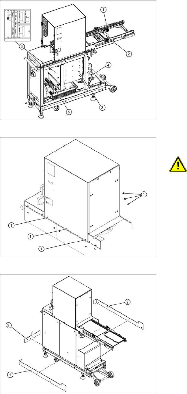
3.2 Overview of Main Assemblies
Overview
1. Feed axis
2. Drive unit – feed axis
3. Lifting axis with tower
4. Drive unit – lifting axis
5. Power supply
6. Control unit (position when fitted)
Screws sealed with locking varnish on
tower
ATTENTION: Do not open screws on
the tower which have been sealed
with locking varnish
The tower is set with these 6 screws (1)
at the factory.
X If you open these screws, the WPC4
must be taken to ASM AS for
readjustment.
Bottom cover plates
If the WPC4 is configured for high machine
heights, additional cover plates will be attached to
the base.
1. Right-hand cover
2. Left-hand cover
3. Front cover
You may need to remove these covers before
performing service work.