00195346-0302_SM_WPC4_EN.pdf - 第44页
Replacing Spare Parts Limit Switches, Sensors and Light Barriers Introduction 44 Ser vice Manual SIPLACE WPC4 3.6.1.3 Requirement s for Settings NOTE: The collision light barriers for height checks must not trigger durin…
Replacing Spare Parts
Introduction Limit Switches, Sensors and Light Barriers
Service Manual SIPLACE WPC4
43
3.6.1.2 General Installation/Removal Instructions
Tools and equipment required
Standard tool
SIPLACE D1 detailed circuit diagrams [00194841-xx] German
SIPLACE D1 detailed circuit diagrams [00194841-xx] English
Cable ties
Cable routing
The cables are fixed and collected together with cable ties. Remove any cable ties which you do not need
with suitable wire cutters. Note how the cables are run and the position of the cable ties. Fix new cable
ties in the same positions as the old ones.
Some cables will be fixed with cable clamps which are held by a socket-head screw. Note how the cables
are run and fit the cable clamps with the socket-head screw in the same positions as they were before.
ATTENTION: Take care not to damage the cables.
Make sure that the cables do rub against any parts and that they are not pinched or damaged
when the lifting and feed axes move.
X Make sure that the cables are fixed with cable ties and/or clamps.
X Make sure that the cables do not rub against any parts and are not pinched when the lifting
and feed axes move.
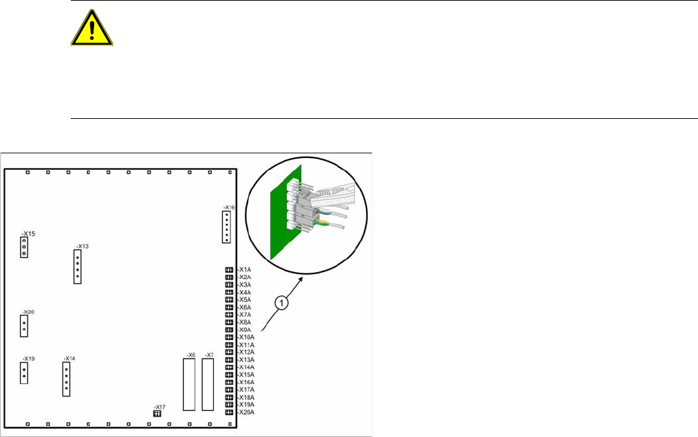
Note the terminal assignment.
All sensor cables lead to the back plane of the
control unit and are connected to the right-hand
terminal strip there - X1a to X13a (1) .
X Check whether all cables are labeled.
X Make sure that you are able to correctly assign
all cables and plugs again. Where necessary,
label cables, plugs and connections for easier
reconnection later.
X Carefully disconnect the required connections
from the relevant terminal (1) with a suitable
pair of pliers (e.g. combination pliers). Make
sure that you do not bend the contact pins.
Replacing Spare Parts
Limit Switches, Sensors and Light Barriers Introduction
44 Service Manual SIPLACE WPC4
3.6.1.3 Requirements for Settings
NOTE: The collision light barriers for height checks must not trigger during calibration
During calibration of the reference sensors and the limits switches, make sure that the collision
light barriers do not trigger without good reason. If this does happen, the calibration process will
stop and no values or invalid values will be calculated.
X During calibration, make sure that the light beam of the collision light barriers is not
interrupted by objects etc..
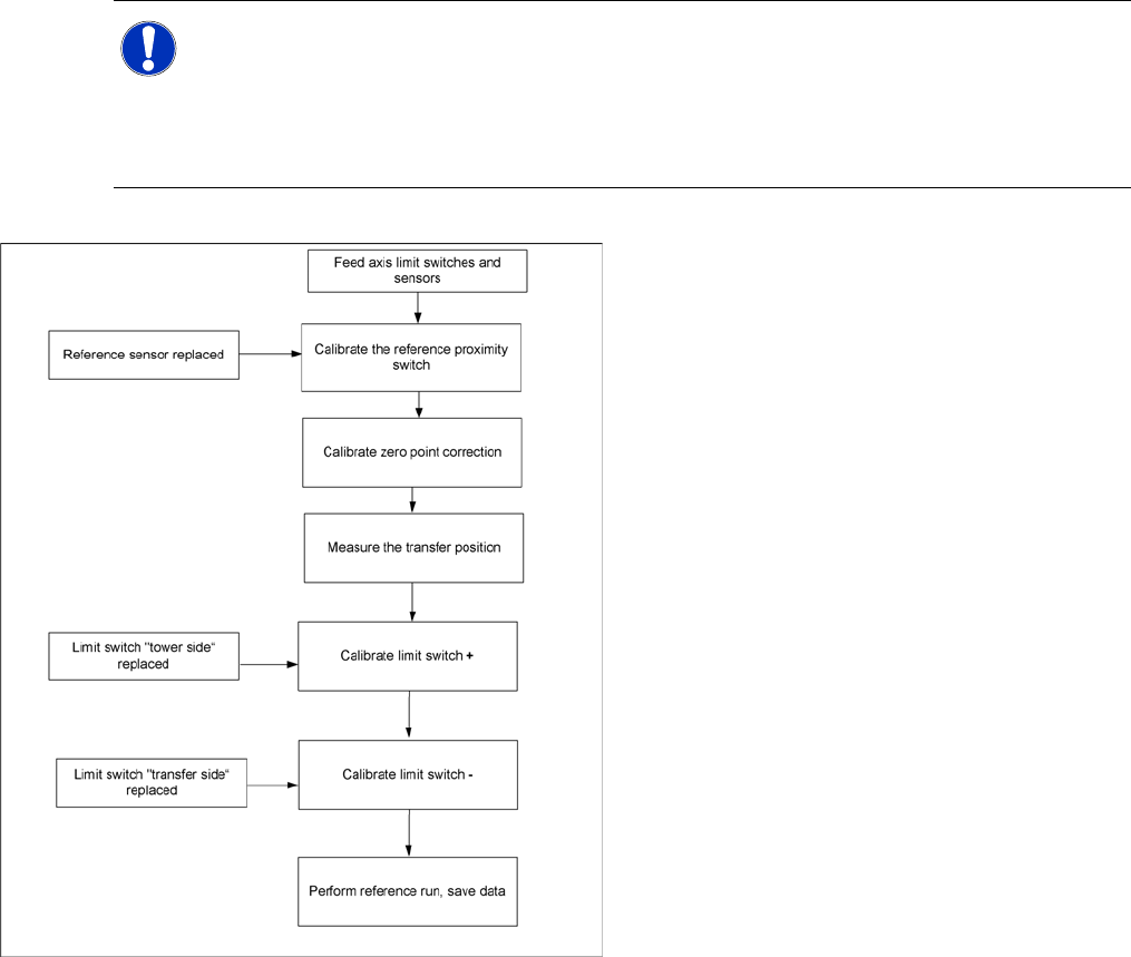
Feed axis – order of settings
If the limit switches or sensors are replaced, you
will need to recalibrate or reset these. Make sure
that you adhere to the correct order. For example,
if the reference sensor is replaced, the subsequent
calibrations, such as "transfer position“ limit switch
+“ etc., must be performed.
Replacing Spare Parts
Introduction Limit Switches, Sensors and Light Barriers
Service Manual SIPLACE WPC4
45
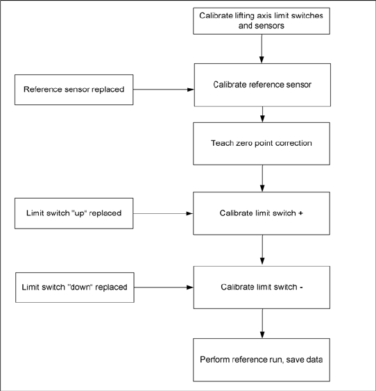
Lifting axis – order of settings
If the limit switches or sensors are replaced, you
will need to recalibrate or reset these. Make sure
that you adhere to the correct order. For example,
if the reference sensor is replaced, the subsequent
calibrations, such as "transfer position“ limit switch
+“ etc., must be performed.