00195346-0302_SM_WPC4_EN.pdf - 第38页
Replacing Spare Parts Control Unit and Power Supply Unit Power Supply U nit 38 Ser vice Manual SIPLACE WPC4 3.5.2 Power Supply Unit 3.5.2.1 Replacing the Pro tective Cont actor Combination (SSK) [00372649-xx] Overview of…
Replacing Spare Parts
Control Unit Control Unit and Power Supply Unit
Service Manual SIPLACE WPC4
37
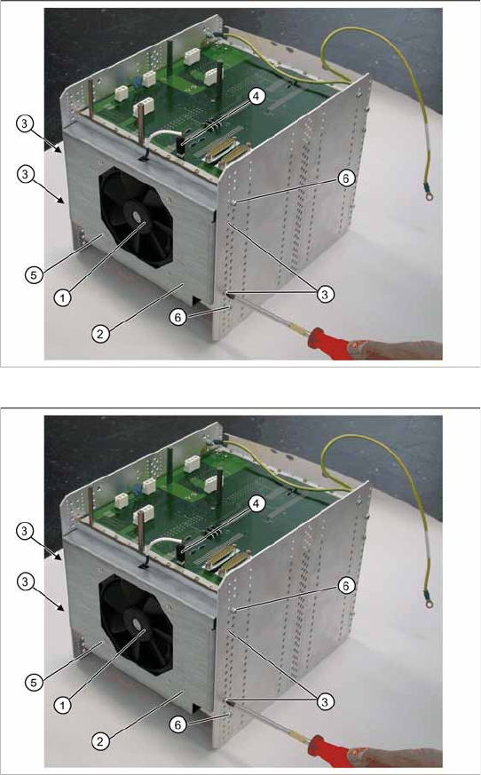
3.5.1.8 Replacing the Fan [03051368-xx]
X Lever the mounting frame (2) out of the control unit holes with a suitable tool (e.g. screwdriver).
X Remove the mounting frame with fan.
X Mark the installation position of the fan (1) in the mounting frame. Make a note of the direction in
which air is blown out! The fan takes air from below and blows it into the inside of the control unit.
X Loosen the 4 screws (5) fastening the fan (1) to the mounting frame.
X Remove the fan.
Installation
X Fit the fan in the mounting frame. Note the position of the connection cable.
X Carefully lever the mounting frame with its openings into the holes.
X Fit the mounting frame with the fan in the control unit.
X Tighten the two screws (6) on the control unit and reconnect to the power supply.
X Fit the complete control unit (see Section (3.5.1.7 Replacing the Complete Control Unit [03047226-
xx]
J
35) ).
Settings
X Check the flow of air from the fan. The fan takes in air from below and blows it into the inside of the
control unit.
Spare part
Control unit fan [03051368-01]
Overview
The fan (1) is located on the underside of the
control unit and is fitted with the help of a mounting
frame (2).
1. Fan
2. Mounting frame
3. 4 x mounting frame fastening screws
4. Electrical connection for fan
5. 4 x fastening screws for fan on mounting frame
Removal
X Dismantle the complete control unit (see Sec-
tion (3.5.1.7 Replacing the Complete Control
Unit [03047226-xx]
J
35) ).
X Unplug the connection cable (4) and the back
plane X17.
X Mark the installation position of the mounting
frame (2) on the relevant control unit holes.
X Loosen the 4 fastening screws (3) on the
mounting frame (2).
X The mounting frame (2) can be levered more
easily out of the holes, if you also loosen the 2
screws (6) on the control unit.
Replacing Spare Parts
Control Unit and Power Supply Unit Power Supply Unit
38 Service Manual SIPLACE WPC4
3.5.2 Power Supply Unit
3.5.2.1 Replacing the Protective Contactor Combination (SSK) [00372649-xx]
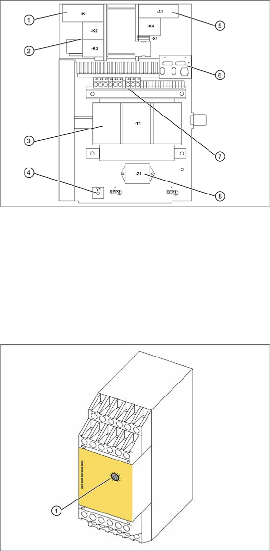
Overview of power supply - view from
above
1. Protective contactor combination SSK
2. Contactors K2/K3
3. Transformer
4. Rectifier bridge
5. Inrush current limitation board A1 with K4
6. Plug/interface to front (emergency stop/main
switch etc.)
7. Primary and secondary transformer fuses
8. Line filter for 3-phase system
X For connection details and complete circuit
diagrams, please refer to the following
documentation:
SIPLACE D1 detailed circuit diagrams
[00194841-xx] German
SIPLACE D1 detailed circuit diagrams
[00194841-xx] English
The protective contactor combination (SSK) is
located at the front of the electrical unit (see Sec-
tion (3.5.2 Power Supply Unit
J
38) ).
1. Setting screw
Spare part
Protective contactor combination (SSK)
3TK2828-1BB41 [00372649-01]
Removal/installation
X Label all connections for easier installation
later.
X Unplug all connections from the protective
contactor combination.
X Lever the protective contactor combination off
the mounting rail.
X Connect the new protective contactor
combination to the mounting rail and restore
the electrical connections.
Settings
X Adjust the setting screw (1) to a value of 0.5
(seconds). If the value is set too high, an error
message will be issued.
X Seal the setting screw with locking varnish.
Replacing Spare Parts
Power Supply Unit Control Unit and Power Supply Unit
Service Manual SIPLACE WPC4
39
3.5.2.2 Replacing the Inrush current Limitation Board [03047752-xx]
The inrush current limitation board is located at the back of the electrical unit (see Section (3.5.2 Power
Supply Unit
J
38) ).
Spare part
Inrush current limitation board WPC4 [03047752-01]
Removal/installation
X Label all connections for easier installation later.
X Unplug all connections from the inrush current limitation board.
X Lever the inrush current limitation board off the mounting rail.
X Connect the new inrush current limitation board to the mounting rail and restore the electrical
connections.
Settings
There are no settings required.