00195346-0302_SM_WPC4_EN.pdf - 第48页
Replacing Spare Parts Limit Switches, Sensors and Light Ba rriers Replacing the WPTC Present in Tower Sensor [0304 7284-xx] 48 Ser vice Manual SIPLACE WPC4 3.6.4 Replacing the WPTC Present in T ower Sensor [03047284-xx] …
Replacing Spare Parts
Replacing the WPTC Lock Sensor Closed [03047285-xx] Limit Switches, Sensors and Light Barriers
Service Manual SIPLACE WPC4
47
3.6.3 Replacing the WPTC Lock Sensor Closed [03047285-xx]
Settings
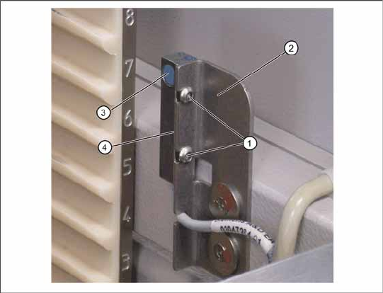
X The sensor must be fitted so that it switches reliably when the locking strip (5) is closed.
X Close and open the locking strip (5) manually. The sensor must switch when the lock is closed.
X The LED on the sensor will show the status:
LED shines = switched
LED does not shine = not switched.
X Use SITEST to check whether the correct output was switched.
X To do this, open the SITEST main view and select the function=>
SITEST inputs/outputs 1
.
The display
WPTC lock sensor closed
must be active.
X Open the lock.
The relevant display must be off.
Spare part
Anti-twist lock proximity switch for magazine
carrier [03047285-01]
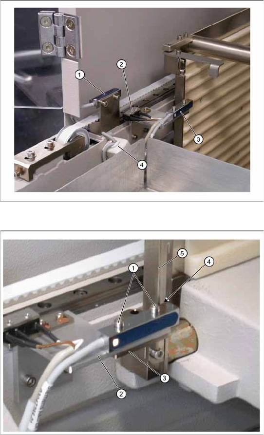
Overview
1. Reference sensor, feed axis
2. Feed axis limit switch on tower side
3. WPTC lock sensor closed
4. Ferrite core for EMC interference suppression
at feed axis reference sensor
Removal/installation
X Loosen the two fastening screws (1) on the
sensor.
X Watch the plate beneath (3). Make sure that it
does not fall out and get lost.
X Loosen the cable clamps and remove the
cable ties.
X Unthread the connection cable as far as the
control unit back plane and unplug it from the
terminal strip.
X Fit the sensor so that the sensor surface (4)
points to the locking strip (5).
X Align the sensor parallel to the mounting
bracket (2). Do not dismantle the mounting
bracket.
X Restore the electrical connection and fix the
connection cable into place.
Replacing Spare Parts
Limit Switches, Sensors and Light Barriers Replacing the WPTC Present in Tower Sensor [03047284-xx]
48 Service Manual SIPLACE WPC4
3.6.4 Replacing the WPTC Present in Tower Sensor [03047284-xx]
Settings
X Check the sensor function.
X To do this, push a waffle pack tray carrier (WPTC) by hand into the tower. The sensor must switch
when the waffle pack tray moves past it.
X Move the waffle pack tray back and forth inside the tower guidance. The sensor must switch reliably.
X Move the waffle pack tray to the right and left inside the tower guidance. The sensor must recognize
the WPTC reliably. The LED on the sensor must shine continuously.
X The LED on the sensor will show the status:
LED shines = switched
LED does not shine = not switched.
X Use SITEST to check whether the correct output was switched.
X To do this, open the SITEST main view and select the function=>
SITEST inputs/outputs 1
.
The display
WPTC present in tower sensor
must be active.
X Remove the waffle pack tray.
The relevant display must be off.
Spare part
Waffle pack tray proximity switch in memory
[03047284-01]
Removal/installation
X Loosen the two screws (1) fastening the
sensor mounting bracket (2).
X Loosen the cable clamps and remove the
cable ties.
X Unthread the connection cable as far as the
control unit back plane and unplug it from the
terminal strip.
X Fit the sensor so that the sensor surface (4)
points to the side.
X Align the sensor parallel to the mounting
bracket (2). Do not dismantle the mounting
bracket.
X Restore the electrical connection and fix the
connection cable into place.
Replacing Spare Parts
Replacing the Reference Sensor, Feed Axis [03047273-xx] Limit Switches, Sensors and Light Barriers
Service Manual SIPLACE WPC4
49
3.6.5 Replacing the Reference Sensor, Feed Axis [03047273-xx]
Installation
X Loosely screw the reference sensor onto the mounting bracket.
X Note the installation position. The sensor surface must point downwards.
X Run the connection cable through the feed-through hole in the mounting bracket. This cable feed-
through hole serves as a strain relief for the connection cable.
X Fit the mounting bracket with the two fastening screws.
X Leave a sufficiently large loop of cable, so that you can fit the cable in the ferrite core.
X Align the reference sensor parallel to the top edge of the mounting bracket and tighten the two
fastening screws on the reference sensor.
Spare part
Reference point proximity switch for feed axis
[03047273-01]
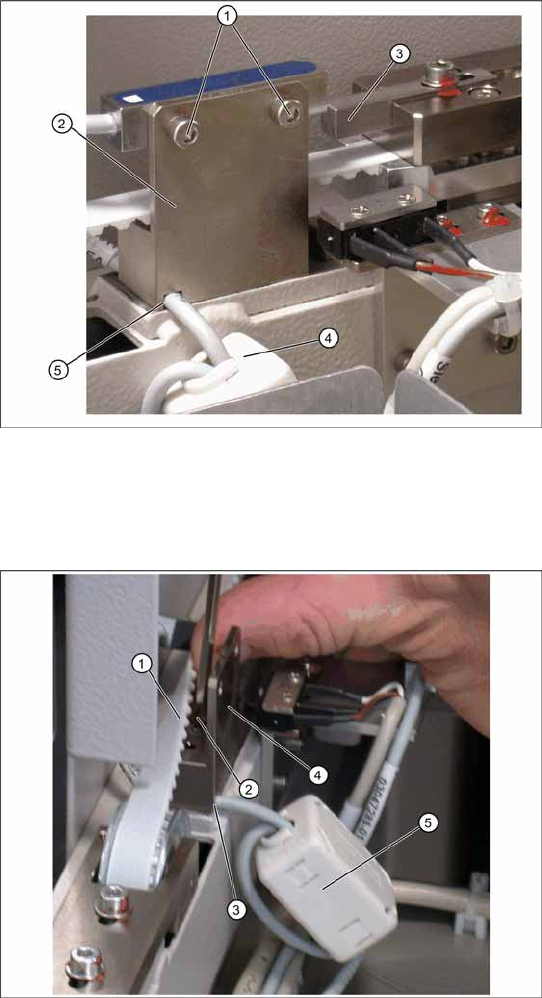
Overview
1. Reference sensor fastening screws
2. Mounting bracket
3. Actuator
4. Ferrite core for EMC interference suppression
at feed axis reference sensor
5. Cable feed-through hole on mounting bracket
Removal
X Loosen the two screws (1) fastening the
proximity switch mounting bracket (3).
X In order to remove the cable at the cable feed-
through hole (5), you need to also remove the
mounting bracket (2).
X Loosen the two screws (1) sealed with locking
varnish, which fasten the reference sensor
mounting bracket.
X To do this, you need to push the feed axis
toothed belt (2) a little to the side, so that you
can reach the two fastening screws (1) . Make
sure that the toothed belt is not buckled or
damaged.
X Remove the connection cable at the cable
feed-through hole (3) on the mounting bracket
(4).
X Open the ferrite core (5) at the fixtures
provided, with the help of a screwdriver.
X Unthread the cable clamp and remove the
ferrite core. Keep these in a safe place for later
installation.
X Unthread the connection cable as far as the
control unit back plane and unplug it from the
terminal strip.