00195346-0302_SM_WPC4_EN.pdf - 第35页
Replacing Spare Parts Control Unit Control Unit and Pow er Supply Unit Service Manual SIPLACE WPC4 35 3.5.1.7 Replacing the Complete Control Unit [030472 26-xx] Overvi ew 1. Control unit – front 2. CAN bus connection on …

Replacing Spare Parts
Control Unit and Power Supply Unit Control Unit
34 Service Manual SIPLACE WPC4
3.5.1.5 Replacing the Servo Amplifier [03048005-xx]
Spare parts
Servo amplifier TBS 200/3Z1 [03048005-01] for feed axis
Servo amplifier TBS 200/10X1 [03048004-01] for lifting axis
Removal/installation
X Wear the ESD wristband.
X Loosen the 4 screws fastening the plexiglass cover and remove this.
X Press the lock under the board of the relevant servo amplifier (see Section (3.5.1 Control Unit
J
31)
)
.
X Carefully pull the servo amplifier out of the control unit.
X Make sure that the servo amplifier matches the relevant axis. Compare the part numbers of the "old"
servo amplifier with those of the new one.
X Carefully insert the new servo amplifier.
X Make sure that the servo amplifier engages properly.
X Refit the plexiglass cover and screw into place.
Settings
There are no settings required.
3.5.1.6 Replacing the Ballast Circuit [00344207-xx]
Spare part
Ballast circuit LZS200/1000 [00344207-02]
Removal/installation
X Wear the ESD wristband.
X Loosen the 4 screws fastening the plexiglass cover and remove this.
X Press the lock on the ballast circuit (see Section (3.5.1 Control Unit
J
31) ).
X Carefully pull the ballast circuit out of the control unit.
X Carefully insert the new ballast circuit.
X Make sure that the ballast circuit engages properly.
X Refit the plexiglass cover and screw into place.
Settings
There are no settings required.
NOTE: Ballast circuit with integrated micro fuse
There is a micro fuse T 10A/440V on the ballast circuit.
X Check this fuse for continuity with the help of a digital multimeter and replace if necessary.
Replacing Spare Parts
Control Unit Control Unit and Power Supply Unit
Service Manual SIPLACE WPC4
35
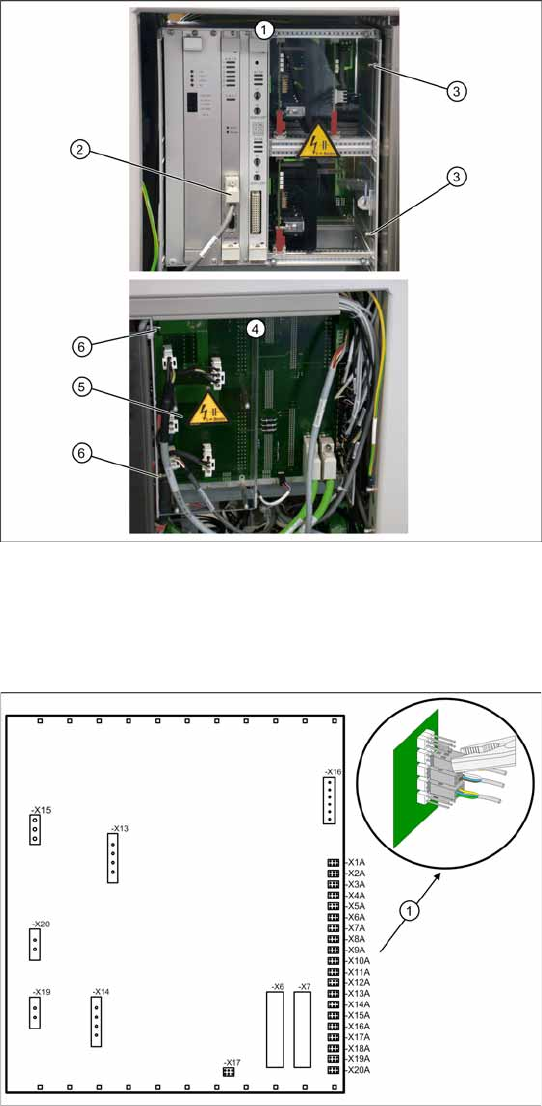
3.5.1.7 Replacing the Complete Control Unit [03047226-xx]
Overview
1. Control unit – front
2. CAN bus connection on controller board
3. 2 x cap nuts on the front
4. Control unit – back plane
5. Plexiglass cover
6. 2 x cap nuts on the back
Spare part
WPC control unit, compl. [03047226-01]
Removal
X Wear the ESD wristband.
X Loosen the 4 screws fastening the plexiglass
cover (5) to the back plane and remove this.
X Check whether all cables are labeled.
X Make sure that you are able to correctly assign
all cables and plugs. Where necessary, label
cables, plugs and connections for easier
reconnection later.
X Unplug the CAN bus cable from the front of the
controller board.
Control unit back plane – details
1. Connections for limit switches, sensors and
light barriers
X For connection details and complete circuit
diagrams, please refer to the following
documentation:
SIPLACE D1 detailed circuit diagrams
[00194841-xx] German
SIPLACE D1 detailed circuit diagrams
[00194841-xx] English
X Carefully unplug connections X1A to X20A on
the terminal strip (proximity switch, sensors
etc.) with a suitable pair of pliers (e.g.
combination pliers) (1). Make sure that you do
not bend the contact pins.
X Unplug the remaining cables, plugs and
connections.
Replacing Spare Parts
Control Unit and Power Supply Unit Control Unit
36 Service Manual SIPLACE WPC4
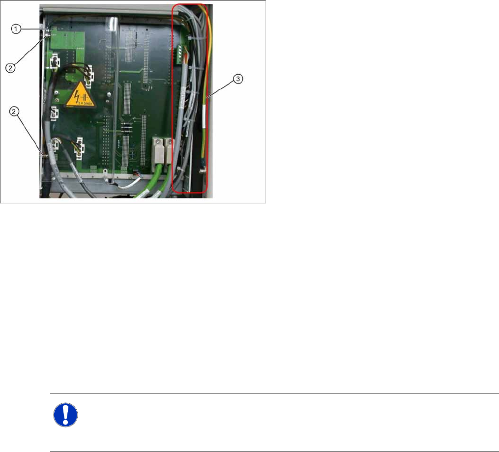
Installation
X During installation, make sure you fit the parts in the correct position (front/back).
X Carefully lift the new control unit onto the threaded pins and fix in place with the 4 cap nuts.
X Restore all electrical connections and plug in the ground cable (1) again.
X Run the cables neatly inside the control unit (3) so that they do not interfere with any other parts.
X Fix the cables with cable ties.
X Fit the plexiglass cover.
Settings
X Use SITEST to check that the sensors have a correct cable assignment. To do this, open the SITEST
main view and select the function=>
SITEST inputs/outputs 1
. Trigger the individual limit switches
and sensors manually, to check whether the correct input is activated.
X Disconnect the control unit ground cable (1)
from the WPC4 frame.
X Loosen the 2 cap nuts (2) from the threaded
pins on the back plane side of the control unit.
X Loosen the 2 cap nuts from the threaded pins
on the front side of the control unit.
X Carefully pull the control unit out towards the
front.
NOTE: Machine data and calibration
If you have also replaced the controller board or axis controller board, together with the control
unit, you will need to perform a firmware download (BIOS and application).
If there is no current MA file available, you will need to completely recalibrate the WPC4.