00195346-0302_SM_WPC4_EN.pdf - 第42页
Replacing Spare Parts Limit Switches, Sensors and Light Barriers Introduction 42 Ser vice Manual SIPLACE WPC4 3.6 Limit Switches, Sens ors and Light Barriers 3.6.1 Introduction 3.6.1.1 Overview Diagram of position - WPC4…
Replacing Spare Parts
Power Supply Unit Control Unit and Power Supply Unit
Service Manual SIPLACE WPC4
41
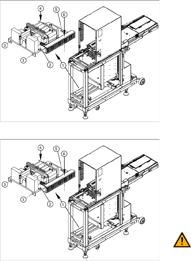
3.5.2.4 Replacing the Complete Power Supply Unit [03047298-xx]
X Remove all cable fixtures (cable ties etc.) and disconnect all cables and plugs from the power supply
unit.
X For connection details and complete circuit diagrams, please refer to the following documentation:
SIPLACE D1 detailed circuit diagrams [00194841-xx] German
SIPLACE D1 detailed circuit diagrams [00194841-xx] English
X Loosen the 4 fastening screws (3), (4) and (6).
X Disconnect the ground terminal (5) from the installation plate of the power supply unit.
X Remove the installation plate with the complete power supply unit from the WPC4, by pulling the
power supply unit out to the side.
X The power supply assemblies are now accessible for further service work, such as replacement of
the mains filter, rectifiers or transformers.
Overview
The power supply assemblies (1), such as the
transformer, relays and contactors, inrush current
limitation board etc. are fitted on an installation
plate (2) and can be removed as a complete unit.
The installation plate is fixed with 4 screws to the
WPC4 frame:
2 x side, front (3)
1 x on frame, left side (4)
1x on frame, right side - in cable duct (6)
Removal
X To gain better access to the power supply unit,
dismantle the side covers and, if necessary,
the front cover. See Section (3.5.2.3 Remo-
ving the Front Cover Plate with Main Switch
and the Emergency Stop Button
J
40) .
X Check whether all cables are labeled.
X Make sure that you are able to correctly assign
all cables and plugs again. Where necessary,
label cables, plugs and connections for easier
reconnection later.
WARNING: Voltage at cable to main
switch
When the WPC4 power cable is
connected and the main switch has
been turned off, voltage is still present
at the cable to the main switch, at the
mains filter and at the terminals to the
main switch.
X Disconnect the WPC4 from the
power supply.
Replacing Spare Parts
Limit Switches, Sensors and Light Barriers Introduction
42 Service Manual SIPLACE WPC4
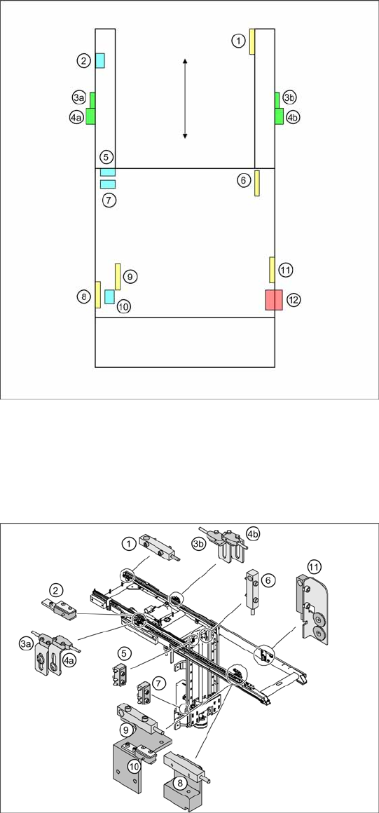
3.6 Limit Switches, Sensors and Light Barriers
3.6.1 Introduction
3.6.1.1 Overview
Diagram of position - WPC4 viewed from
above
1= WPTC available sensor
2 = Feed axis limit switch on transfer side
3a = Collision light barrier for normal components
(receiver) with LED
3b = Collision light barrier for normal components
(transmitter) with LED
4a = Collision light barrier for high components
(transmitter)
4b = Collision light barrier for high components
(receiver) with LED
5 = Top limit switch for lifting axis
6 = Reference sensor, lifting axis
7 = Bottom lifting axis limit switch (not accessible if
lifting axis down)
8 = Reference sensor, feed axis
9 = WPTC lock sensor closed
10 = Feed axis limit switch on tower side
11 = WPTC present in tower sensor
12= Locking switch for door
Position - WPC4 detail view
Legend as above.
Replacing Spare Parts
Introduction Limit Switches, Sensors and Light Barriers
Service Manual SIPLACE WPC4
43
3.6.1.2 General Installation/Removal Instructions
Tools and equipment required
Standard tool
SIPLACE D1 detailed circuit diagrams [00194841-xx] German
SIPLACE D1 detailed circuit diagrams [00194841-xx] English
Cable ties
Cable routing
The cables are fixed and collected together with cable ties. Remove any cable ties which you do not need
with suitable wire cutters. Note how the cables are run and the position of the cable ties. Fix new cable
ties in the same positions as the old ones.
Some cables will be fixed with cable clamps which are held by a socket-head screw. Note how the cables
are run and fit the cable clamps with the socket-head screw in the same positions as they were before.
ATTENTION: Take care not to damage the cables.
Make sure that the cables do rub against any parts and that they are not pinched or damaged
when the lifting and feed axes move.
X Make sure that the cables are fixed with cable ties and/or clamps.
X Make sure that the cables do not rub against any parts and are not pinched when the lifting
and feed axes move.
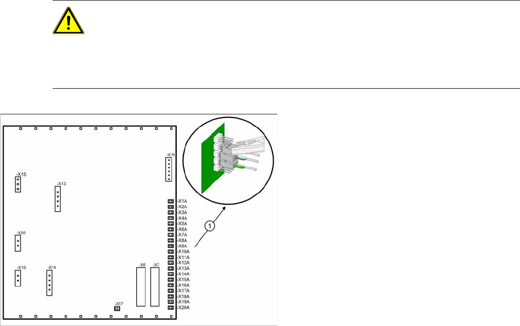
Note the terminal assignment.
All sensor cables lead to the back plane of the
control unit and are connected to the right-hand
terminal strip there - X1a to X13a (1) .
X Check whether all cables are labeled.
X Make sure that you are able to correctly assign
all cables and plugs again. Where necessary,
label cables, plugs and connections for easier
reconnection later.
X Carefully disconnect the required connections
from the relevant terminal (1) with a suitable
pair of pliers (e.g. combination pliers). Make
sure that you do not bend the contact pins.