5TROUBLESHOOTING_.pdf - 第104页
3.3 . 1 Reset Procedure from Component Recognition Error ( 1 L 35 ) Order of Error Codes ( Display C ) • ( Display A ) • ( Display B ) • ( Cause ) _ ( Remedy ) ( Display C ) 1 L 353010 019 ( Display A ) Lead Detection Er…
3.3
.
1
Reset
Procedure
from
Component
Recognition
Error
(
1
L
34
)
Order
of
Error
Codes
(
Display
C
)
•
(
Display
A
)
•
(
Display
B
)
•
(
Cause
)
•
(
Remedy
)
(
Display
C
)
1
L
34
B
020
029
(
Display
A
)
Corner
Detection
Error
1
L
34
••
•
•
(
Display
B
)
NOZZLE
PROTRUSION
OCCUPIES
MORE
THAN
2
CORNERS
.
(
Display
C
)
1
L
34
B
030
039
(
Display
A
)
Corner
Detection
Error
(
Display
B
)
RECOGNITION
ABORTED
BECAUSEjOF
lMPROPER
COMPONENT
HANDLING
.
(
Display
C
)
1
L
34
B
500
509
(
Display
A
)
Corner
Detection
Error
(
Display
B
)
CORNER
(
UPPER
-
LEFT
)
NOT
FOUND
.
(
Display
C
)
1
L
34
B
600
609
(
Display
A
)
Corner
Detection
Error
(
Display
B
)
CORNER
(
LOWER
:
LEFT
)
NOT
FOUND
.
(
Display
C
)
1
L
34
B
700
709
(
Display
A
)
Comer
Detection
Error
(
Display
B
)
CORNER
(
UPPER
-
RIGHT
)
NOT
FOUND
.
(
Display
C
)
1
L
34
B
800
809
(
Display
A
)
Corner
Detection
Error
(
Display
B
)
CORNER
(
LOWER
-
RIGHT
)
NOT
FOUND
.
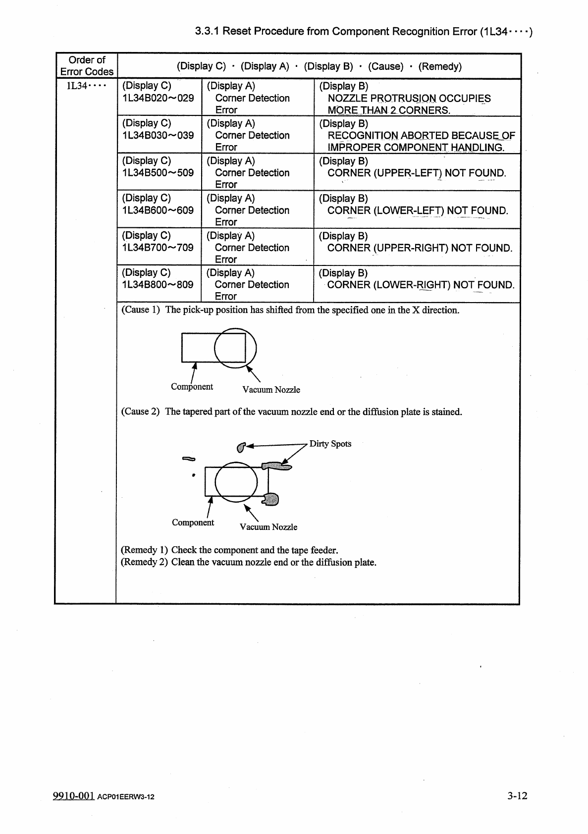
(
Cause
1
)
The
pick
-
up
position
has
shifted
from
the
specified
one
in
the
X
direction
.
Component
Vacuum
Nozzle
(
Cause
2
)
The
tapered
part
of
the
vacuum
nozzle
end
or
the
diffusion
plate
is
stained
.
Dirty
Spots
Component
(
Remedy
1
)
Check
the
component
and
the
tape
feeder
.
(
Remedy
2
)
Clean
the
vacuum
nozzle
end
or
the
difiusion
plate
.
9910
-
001
ACP
01
EERW
3
-
12
3
-
12
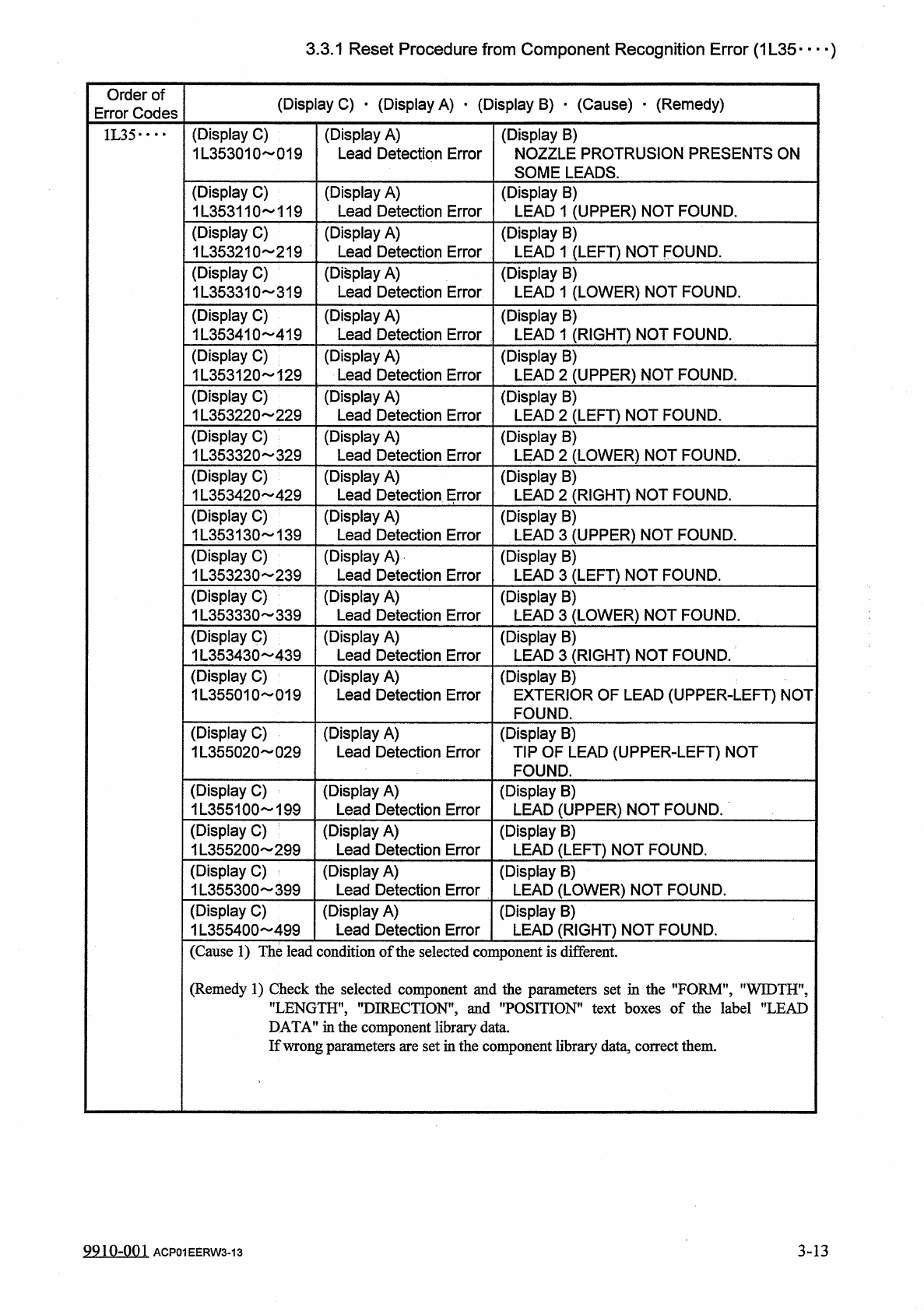
3.3
.
1
Reset
Procedure
from
Component
Recognition
Error
(
1
L
35
)
Order
of
Error
Codes
(
Display
C
)
•
(
Display
A
)
•
(
Display
B
)
•
(
Cause
)
_
(
Remedy
)
(
Display
C
)
1
L
353010
019
(
Display
A
)
Lead
Detection
Error
(
Display
B
)
NOZZLE
PROTRUSION
PRESENTS
ON
SOME
LEADS
.
1
L
35
•
…
(
Display
C
)
1
L
353110
119
(
Display
A
)
Lead
Detection
Error
(
Display
B
)
LEAD
1
(
UPPER
)
NOT
FOUND
.
(
Display
C
)
1
L
353210
219
(
Display
A
)
Lead
Detection
Error
(
Display
B
)
LEAD
1
(
LEFT
)
NOT
FOUND
.
(
Display
C
)
1
L
353310
319
(
Display
A
)
Lead
Detection
Error
(
Display
B
)
LEAD
1
(
LOWER
)
NOT
FOUND
.
(
Display
C
)
1
L
353410
419
(
Display
A
)
Lead
Detection
Error
(
Display
B
)
LEAD
1
(
RIGHT
)
NOT
FOUND
.
(
Display
C
)
1
L
353120
129
(
Display
A
)
Lead
Detection
Error
(
Display
B
)
LEAD
2
(
UPPER
)
NOT
FOUND
.
(
Display
C
)
1
L
353220
229
(
Display
A
)
Lead
Detection
Error
(
Display
B
)
LEAD
2
(
LEFT
)
NOT
FOUND
.
(
Display
C
)
353320
329
(
Display
A
)
Lead
Detection
Error
(
Display
B
)
LEAD
2
(
LOWER
)
NOT
FOUND
.
(
Display
C
)
1
L
353420
429
(
Display
A
)
Lead
Detection
Error
(
Display
B
)
LEAD
2
(
RIGHT
)
NOT
FOUND
.
(
Display
C
)
1
L
353130
139
(
Display
A
)
Lead
Detection
Error
(
Display
B
)
LEAD
3
(
UPPER
)
NOT
FOUND
.
(
Display
C
)
1
L
353230
239
(
Display
A
)
Lead
Detection
Error
(
Display
B
)
LEAD
3
(
LEFT
)
NOT
FOUND
.
(
Display
C
)
U
353330
339
(
Display
A
)
Lead
Detection
Error
(
Display
B
)
LEAD
3
(
LOWER
)
NOT
FOUND
.
(
Display
C
)
1
L
353430
439
(
Display
A
)
Lead
Detection
Error
(
Display
B
)
LEAD
3
(
RIGHT
)
NOT
FOUND
.
(
Display
C
)
1
L
355010
019
(
Display
A
)
Lead
Detection
Error
(
Display
B
)
EXTERIOR
OF
LEAD
(
UPPER
-
LEFT
)
NOT
FOUND
.
(
Display
C
)
1
L
355020
029
(
Display
A
)
Lead
Detection
Error
(
Display
B
)
TIP
OF
LEAD
(
UPPER
-
LEFT
)
NOT
FOUND
.
(
Display
C
)
1
L
355100
199
(
Display
A
)
Lead
Detection
Error
(
Display
B
)
LEAD
(
UPPER
)
NOT
FOUND
.
(
Display
C
)
1
L
355200
299
(
Display
A
)
Lead
Detection
Error
(
Display
B
)
LEAD
(
LEFT
)
NOT
FOUND
.
(
Display
C
)
1
L
355300
399
(
Display
A
)
Lead
Detection
Error
(
Display
B
)
LEAD
(
LOWER
)
NOT
FOUND
.
(
Display
C
)
1
L
355400
499
(
Display
A
)
Lead
Detection
Error
(
Display
B
)
LEAD
(
RIGHT
)
NOT
FOUND
.
(
Cause
1
)
The
lead
condition
of
the
selected
component
is
different
.
(
Remedy
1
)
Check
the
selected
component
and
the
parameters
set
in
the
"
FORM
'
"
WIDTH
"
"
LENGTH
"
’
DIRECTION
'
and
"
POSITION
"
text
boxes
of
the
label
"
LEAD
DATA
”
in
the
component
library
data
.
If
wrong
parameters
are
set
in
the
component
library
data
,
correct
them
.
9
Q
1
Q
-
0
Q
1
3
-
13
ACP
01
EERW
3
-
13
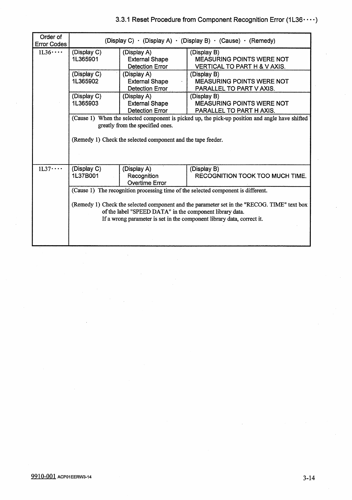
3.3
.
1
Reset
Procedure
from
Component
Recognition
Error
(
1
L
36
—
)
Order
of
Error
Codes
(
Display
C
)
•
(
Display
A
)
-
(
Display
B
)
•
(
Cause
)
_
(
Remedy
)
(
Display
B
)
MEASURING
POINTS
WERE
NOT
VERTICAL
TO
PART
H
&
V
AXIS
.
(
Display
C
)
1
L
365901
(
Display
A
)
External
Shape
Detection
Error
1
L
36
••
•
•
(
Display
C
)
1
L
365902
(
Display
A
)
External
Shape
Detection
Error
(
Display
B
)
MEASURING
POINTS
WERE
NOT
PARALLEL
TO
PART
V
AXIS
.
(
Display
C
)
1
L
365903
(
Display
A
)
External
Shape
Detection
Error
(
Display
B
)
MEASURING
POINTS
WERE
NOT
PARALLEL
TO
PART
H
AXIS
.
(
Cause
1
)
When
the
selected
component
is
picked
up
,
the
pick
-
up
position
and
angle
have
shifted
greatly
from
the
specified
ones
.
(
Remedy
1
)
Check
the
selected
component
and
the
tape
feeder
.
(
Display
C
)
1
L
37
B
001
(
Display
A
)
Recognition
Overtime
Error
(
Display
B
)
RECOGNITION
TOOK
TOO
MUCH
TIME
.
1
L
37
…
(
Cause
1
)
The
recognition
processing
time
of
the
selected
component
is
different
.
(
Remedy
1
)
Check
the
selected
component
and
the
parameter
set
in
the
"
RECOG
.
TIME
"
text
box
of
the
label
"
SPEED
DATA
"
in
the
component
library
data
.
If
a
wrong
parameter
is
set
in
the
component
library
data
,
correct
it
.
9910
-
001
ACP
01
EERW
3
-
14
344