5TROUBLESHOOTING_.pdf - 第96页
3.3 . 1 Reset Procedure from Component Recognition Error ( 1 L 01 ) • Described below is how to decode the error code numbers in the table below . Decoding : * □ * * A * * * TT a b * : Numerals □ : Filled with Symbol f ,…
3.3
.
1
Reset
Procedure
from
Component
Recognition
Error
3.3
Troubleshooting
against
Recognition
Errors
3.3
.
1
Reset
Procedure
from
Component
Recognition
Error
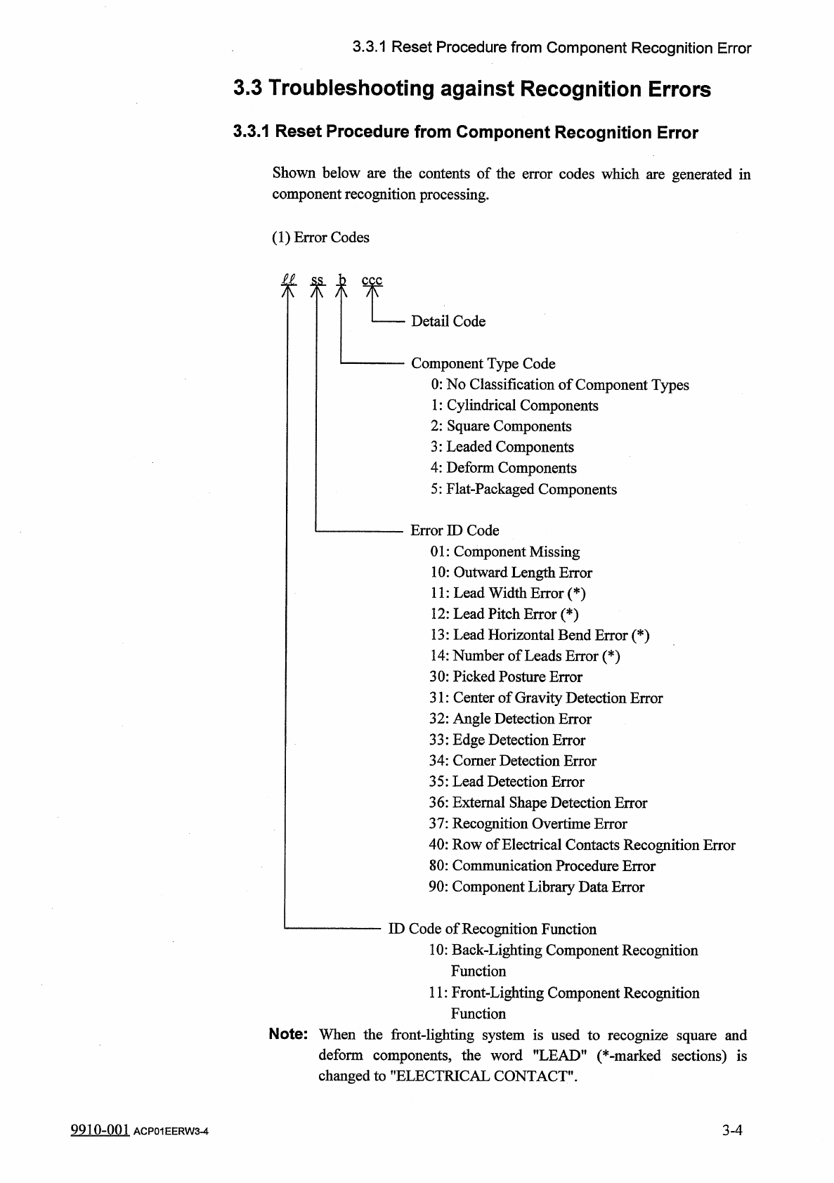
Shown
below
are
the
contents
of
the
error
codes
which
are
generated
in
component
recognition
processing
.
(
1
)
Error
Codes
£
1
ss
,
h
八 八 八
Detail
Code
Component
Type
Code
0
:
No
Classification
of
Component
Types
1
:
Cylindrical
Components
2
:
Square
Components
3
:
Leaded
Components
4
:
Deform
Components
5
:
Flat
-
Packaged
Components
Error
ID
Code
01
:
Component
Missing
10
:
Outward
Length
Error
11
:
Lead
Width
Error
(
*
)
12
:
Lead
Pitch
Error
(
*
)
13
:
Lead
Horizontal
Bend
Error
(
*
)
14
:
Number
of
Leads
Error
(
*
)
30
:
Picked
Posture
Error
31
:
Center
of
Gravity
Detection
Error
32
:
Angle
Detection
Error
33
:
Edge
Detection
Error
34
:
Comer
Detection
Error
35
:
Lead
Detection
Error
36
:
External
Shape
Detection
Error
37
:
Recognition
Overtime
Error
40
:
Row
of
Electrical
Contacts
Recognition
Error
80
:
Communication
Procedure
Error
90
:
Component
Library
Data
Error
ID
Code
of
Recognition
Function
10
:
Back
-
Lighting
Component
Recognition
Function
11
:
Front
-
Lighting
Component
Recognition
Function
Note
:
When
the
front
-
lighting
system
is
used
to
recognize
square
and
deform
components
,
the
word
"
LEAD
"
(
*
-
marked
sections
)
is
changed
to
"
ELECTRICAL
CONTACT
"
.
3
-
4
9910
-
001
ACP
01
EERW
3
-
4
3.3
.
1
Reset
Procedure
from
Component
Recognition
Error
(
1
L
01
)
•
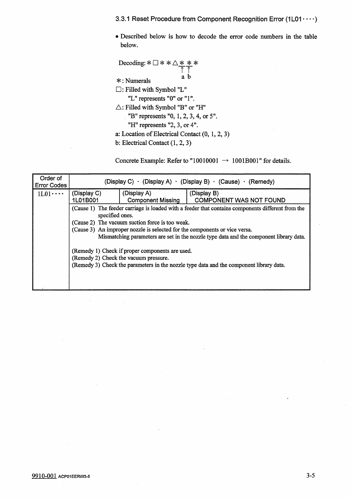
Described
below
is
how
to
decode
the
error
code
numbers
in
the
table
below
.
Decoding
:
*
□
*
*
A
*
*
*
TT
a
b
*
:
Numerals
□
:
Filled
with
Symbol
f
,
LM
"
L
”
represents
"
(
Tori
"
.
△
:
Filled
with
Symbol
?
,
B
,
?
or
MHn
”
B
”
represents
"
0
,
1
,
2
,
3
,
4
,
or
5
'
"
H
"
represents
”
2
,
3
,
or
4
"
.
a
:
Location
of
Electrical
Contact
(
0
,
1
,
2
,
3
)
b
:
Electrical
Contact
(
1
,
2
,
3
)
Concrete
Example
:
Refer
to
”
10010001
—
1001
B
001
”
for
details
.
Order
of
Error
Codes
(
Display
C
)
•
(
Display
A
)
■
(
Display
B
)
■
(
Cause
)
_
(
Remedy
)
(
Display
A
)
Component
Missing
(
Display
C
)
1
L
01
B
001
(
Display
B
)
COMPONENT
WAS
NOT
FOUND
1
L
01
• •
•
•
(
Cause
1
)
The
feeder
carriage
is
loaded
with
a
feeder
that
contains
components
different
from
the
specified
ones
.
(
Cause
2
)
The
vacuum
suction
force
is
too
weak
.
(
Cause
3
)
An
improper
nozzle
is
selected
for
the
components
Mismatching
parameters
are
set
in
the
nozzle
type
data
and
the
component
library
data
.
(
Remedy
1
)
Check
if
proper
components
are
used
,
edy
2
)
Check
the
vacuum
pressure
.
edy
3
)
Check
the
parameters
in
the
nozzle
type
data
and
the
component
library
data
.
(
Remi
(
Remi
3
-
5
9910
-
001
ACP
01
EERW
3
-
5
3.3
.
1
Reset
Procedure
from
Component
Recognition
Error
(
1
L
10
)
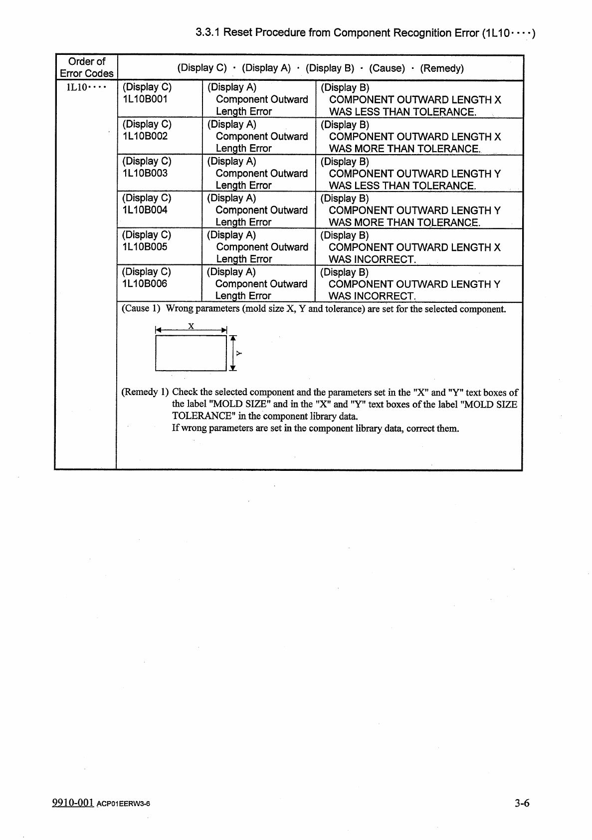
Order
of
Error
Codes
(
Display
C
)
•
(
Display
A
)
_
(
Display
B
)
■
(
Cause
)
■
(
Remedy
)
(
Display
C
)
1
L
10
B
001
(
Display
A
)
Component
Outward
Length
Error
(
Display
B
)
COMPONENT
OUTWARD
LENGTH
X
WAS
LESS
THAN
TOLERANCE
.
1
L
10
•
…
(
Display
C
)
1
L
10
B
002
(
Display
A
)
Component
Outward
Length
Error
(
Display
B
)
COMPONENT
OUTWARD
LENGTH
X
WAS
MORE
THAN
TOLERANCE
.
(
Display
C
)
1
L
10
B
003
(
Display
A
)
Component
Outward
Length
Error
(
Display
B
)
COMPONENT
OUTWARD
LENGTH
Y
WAS
LESS
THAN
TOLERANCE
.
(
Display
C
)
1
L
10
B
004
(
Display
A
)
Component
Outward
Length
Error
(
Display
B
)
COMPONENT
OUTWARD
LENGTH
Y
WAS
MORE
THAN
TOLERANCE
.
(
Display
C
)
1
L
10
B
005
(
Display
A
)
Component
Outward
Length
Error
(
Display
B
)
COMPONENT
OUTWARD
LENGTH
X
WAS
INCORRECT
.
(
Display
C
)
1
L
10
B
006
(
Display
A
)
Component
Outward
Length
Error
(
Display
B
)
COMPONENT
OUTWARD
LENGTH
Y
WAS
INCORRECT
.
(
Cause
1
)
Wrong
parameters
(
mold
size
X
,
Y
and
tolerance
)
are
set
for
the
selected
component
.
X
K
-
H
>
X
(
Remedy
1
)
Check
the
selected
component
and
the
parameters
set
in
the
"
X
”
and
”
Y
”
text
boxes
of
the
label
"
MOLD
SIZE
”
and
in
the
"
X
"
and
"
Y
"
text
boxes
of
the
label
"
MOLD
SIZE
TOLERANCE
"
in
the
component
library
data
.
If
wrong
parameters
are
set
in
the
component
library
data
,
correct
them
.
9910
-
001
ACP
01
EERW
3
-
6
3
-
6