5TROUBLESHOOTING_.pdf - 第63页
2.2 Troubleshooting after Error Display ( L ) ( Display A ) • ( Display B ) • ( Cause ) - ( Remedy ) Order Code ( Display A ) L CONVEYOR WIDTH ORI - ( Display B ) OUTPUT SIGNAL FROM THE PULSE MOTOR DRIVER WAS NOT DETECTE…
2.2
Troubleshooting
after
Error
Display
(
L
)
(
Display
A
)
•
(
Display
B
)
•
(
Cause
)
•
(
Remedy
)
Order
Code
(
Display
A
)
LOAD
POWER
CIRCUIT
(
Display
B
)
THE
AIR
PRESSURE
IS
TOO
LOW
.
;
PS
1
OFF
L
60
-
03
-
02
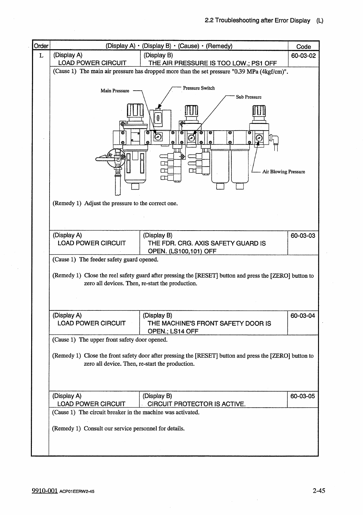
(
Cause
1
)
The
main
air
pressure
has
dropped
more
than
the
set
pressure
"
0.39
MPa
(
4
kgf
/
cm
)
"
.
Pressure
Switch
Main
Pressure
Sub
Pressure
\
@
t
m
I
©
w
o i l
©
TQT
©
©
f
-
!
>
■
□
c
Air
Blowing
Pressure
□
□
O
(
Remedy
1
)
Adjust
the
pressure
to
the
correct
one
.
(
Display
A
)
LOAD
POWER
CIRCUIT
(
Display
B
)
THE
FDR
.
CRG
.
AXIS
SAFETY
GUARD
IS
OPEN
.
(
LS
100
,
101
)
OFF
60
-
03
-
03
(
Cause
1
)
The
feeder
safety
guard
opened
.
(
Remedy
1
)
Close
the
reel
safety
guard
after
pressing
the
[
RESET
]
button
and
press
the
[
ZERO
]
button
to
zero
all
devices
.
Then
,
re
-
start
the
production
.
(
Display
A
)
LOAD
POWER
CIRCUIT
(
Display
B
)
THE
MACHINES
FRONT
SAFETY
DOOR
IS
OPEN
.
;
LS
14
QFF
60
-
03
-
04
(
Cause
1
)
The
upper
front
safety
door
opened
.
(
Remedy
1
)
Close
the
front
safety
door
after
pressing
the
[
RESET
]
button
and
press
the
[
ZERO
]
button
to
zero
all
device
.
Then
,
re
-
start
the
production
.
(
Display
A
)
LOAD
POWER
CIRCUIT
(
Display
B
)
CIRCUIT
PROTECTOR
IS
ACTIVE
.
60
-
03
-
05
(
Cause
1
)
The
circuit
breaker
in
the
machine
was
activated
.
(
Remedy
1
)
Consult
our
service
personnel
for
details
.
9910
-
001
2
-
45
ACP
01
EERW
2
-
45
2.2
Troubleshooting
after
Error
Display
(
L
)
(
Display
A
)
•
(
Display
B
)
•
(
Cause
)
-
(
Remedy
)
Order
Code
(
Display
A
)
L
CONVEYOR
WIDTH
ORI
-
(
Display
B
)
OUTPUT
SIGNAL
FROM
THE
PULSE
MOTOR
DRIVER
WAS
NOT
DETECTED
.
L
0
E
-
01
-
01
GIN
(
Display
A
)
L
CONVEYOR
WIDTH
ORI
-
(
Display
B
)
FEEDBACK
VALUE
IS
INDEFINITE
.
0
E
-
01
-
02
GIN
(
Display
A
)
L
CONVEYOR
WIDTH
ORI
-
(
Display
B
)
THE
L
CONVEYOR
WIDTH
IS
NOT
AT
ORIGIN
.
0
E
-
01
-
03
GIN
(
Cause
1
)
Self
-
Diagnostics
Error
Message
(
Remedy
1
)
Zero
all
devices
by
pressing
the
[
ZERO
]
button
and
then
re
-
start
the
operation
.
(
Display
A
)
L
CONVEYOR
WIDTH
TIMING
(
Display
B
)
TASK
HAS
NOT
BEEN
COMPLETED
UNABLE
TO
CONTINUE
.
0
E
-
02
-
01
(
Cause
1
)
Self
-
Diagnostics
Error
Message
(
Remedy
1
)
Zero
all
devices
by
pressing
the
[
ZERO
]
button
and
then
re
-
start
the
operation
.
(
Display
A
)
L
CONVEYOR
WIDTH
DATA
(
Display
B
)
THE
DRIVER
DATA
WAS
DETECTED
OUTSIDE
OF
THE
POSSIBLE
RANGE
.
0
E
-
03
-
01
(
Cause
1
)
The
"
PRODUCT
CHANGE
"
display
was
opened
and
the
manual
axis
operation
was
performed
to
widen
the
width
from
the
origin
position
.
The
manual
axis
operation
was
performed
to
make
the
width
narrower
than
49
mm
.
(
Remedy
1
)
Cancel
the
error
with
the
[
RESET
]
button
and
perform
the
manual
axis
operation
in
the
cor
-
rect
direction
.
(
Display
A
)
L
CONVEYOR
WIDTH
LIMIT
(
Display
B
)
(
+
)
LIMIT
ERROR
HAS
BEEN
DETECTED
.
;
PHS
114
E
/
NR
0
E
-
04
-
01
(
Display
A
)
L
CONVEYOR
WIDTH
LIMIT
(
Display
B
)
(
•
)
LIMIT
ERROR
HAS
BEEN
DETECTED
.
:
PHS
115
E
/
NR
0
E
-
04
-
02
(
Cause
1
)
An
optical
beam
of
the
sensor
is
shielded
.
(
Cause
2
)
Dirt
adheres
to
the
sensor
and
the
optical
beam
is
shielded
.
(
Cause
3
)
The
sensor
is
defective
.
(
Remedy
1
)
Turn
off
the
power
supply
and
move
the
conveyor
width
with
the
manual
knob
for
easier
operation
.
Re
-
attach
the
light
shield
plate
or
the
sensor
securely
(
remove
the
looseness
)
.
Re
-
supply
power
to
the
machine
and
zero
the
L
conveyor
width
.
Open
the
"
PRODUCT
CHANGE
"
display
and
confirm
that
the
L
conveyor
belts
are
widened
to
the
specified
width
.
If
necessary
,
correct
the
"
CLEARANCE
”
data
for
the
conveyor
width
.
(
Remedy
2
)
Wipe
off
dirt
on
the
sensor
and
zero
the
L
conveyor
again
.
(
Remedy
3
)
Replace
the
sensor
with
a
new
one
.
9910
-
001
2
-
46
ACP
01
EERW
2
-
46
2.2
Troubleshooting
after
Error
Display
(
M
)
(
Display
A
)
•
(
Display
B
)
•
(
Cause
)
•
(
Remedy
)
Order
Code
(
Display
A
)
MASTER
HEAD
OFFSET
(
Display
B
)
LINEAR
MEASURE
SYSTEM
WAS
AT
HIGH
POSITION
.
M
70
76
-
05
-
01
(
Display
A
)
MASTER
HEAD
OFFSET
(
Display
B
)
LINEAR
MEASURE
SYSTEM
WAS
AT
LOW
PO
-
SITION
.
70
76
_
05
-
02
(
Cause
1
)
The
master
nozzle
or
the
linear
measure
detection
sensor
may
not
be
attached
correctly
.
(
Remedy
1
)
Attach
the
master
nozzle
correctly
.
It
is
required
to
adjust
the
linear
measure
sensor
after
it
is
attached
correctly
.
(
Display
A
)
NOZZLE
POSITION
(
Display
B
)
THE
SELECTED
NOZZLE
WAS
ERRONEOUSLY
POSITIONED
.
;
PHS
19
N
63
-
02
-
01
(
Cause
1
)
The
nozzle
in
the
3
-
o
'
clock
direction
moved
down
,
passing
over
the
low
level
at
Station
#
15
and
was
detected
.
(
Cause
2
)
Self
-
Diagnostics
Error
Message
(
Remedy
1
)
As
Head
XX
indicates
the
head
located
at
Station
#
16
,
check
the
head
and
press
the
[
RESET
]
button
to
cancel
the
error
.
Then
,
move
the
feeder
carriage
until
it
is
inserted
deep
inside
from
the
front
side
of
the
machine
.
•
After
the
component
is
placed
on
the
P
.
C
.
B
.
,
press
the
[
STOP
]
button
to
cancel
the
nozzle
bypass
operation
and
check
how
the
nozzle
is
inserted
at
the
front
side
of
the
machine
.
(
Remedy
2
)
Zero
all
devices
by
pressing
the
[
ZERO
]
button
and
then
re
-
start
the
operation
.
When
the
trouble
cannot
be
fixed
,
consult
our
service
personnel
for
the
remedy
.
(
Display
B
)
THE
SELECTED
NOZZLE
LEVEL
WAS
NOT
AT
HIGH
POSITION
.
;
PHS
20
(
Display
A
)
NOZZLE
POSITION
63
-
02
-
02
(
Display
A
)
NOZZLE
POSITION
(
Display
B
)
THE
SELECTED
NOZZLE
LEVEL
WAS
NOT
AT
LOW
POSITION
.
;
PHS
20
63
-
02
-
03
(
Cause
1
)
The
optical
beam
was
not
set
in
the
nE
/
R
"
or
the
HE
/
NRn
condition
due
to
dirt
on
the
sensor
.
(
E
/
R
:
Light
Emitted
and
Received
,
E
/
NR
:
Light
Emitted
and
Not
Received
)
The
sensor
may
be
defective
.
(
Remedy
1
)
Check
that
no
dirt
adheres
to
the
sensor
.
Or
,
it
may
be
necessary
to
replace
the
sensor
with
a
new
one
because
it
may
be
defective
.
Contact
our
service
personnel
before
replacing
the
sensor
.
2
-
47
99
in
-
oni
ACP
01
EERW
2
-
47