5TROUBLESHOOTING_.pdf - 第33页
2.2 Troubleshooting after Error Display ( C ) ( Display A ) • ( Display B ) • ( Cause ) • ( Remedy ) Order Code C ( Display A ) CAMERA DATA ERROR ( Display B ) Note 65 - 07 - 01 Note Note : Refer to , f 3.3 . 4 Reset Pro…
2.2
Troubleshooting
after
Error
Display
(
C
)
(
Display
A
)
•
(
Display
B
)
•
(
Cause
)
(
Remedy
)
Order
Code
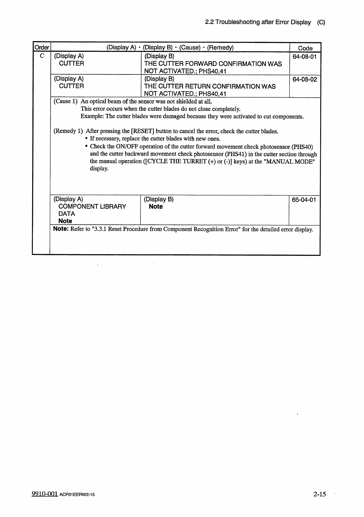
C
(
Display
A
)
CUTTER
(
Display
B
)
THE
CUTTER
FORWARD
CONFIRMATION
WAS
NOT
ACTIVATED
.
;
PHS
40.41
64
-
08
-
01
(
Display
A
)
CUTTER
(
Display
B
)
THE
CUTTER
RETURN
CONFIRMATION
WAS
NOT
ACTIVATED
.
;
PHS
40.41
64
-
08
-
02
(
Cause
1
)
An
optical
beam
of
the
sensor
was
not
shielded
at
all
.
This
error
occurs
when
the
cutter
blades
do
not
close
completely
.
Example
:
The
cutter
blades
were
damaged
because
they
were
activated
to
cut
components
.
(
Remedy
1
)
After
pressing
the
[
RESET
]
button
to
cancel
the
error
,
check
the
cutter
blades
.
•
If
necessary
,
replace
the
cutter
blades
with
new
ones
.
•
Check
the
ON
/
OFF
operation
of
the
cutter
forward
movement
check
photosensor
(
PHS
40
)
and
the
cutter
backward
movement
check
photosensor
(
PHS
41
)
in
the
cutter
section
through
the
manual
operation
(
[
CYCLE
THE
TURRET
(
+
)
or
(
-
)
]
keys
)
at
the
”
MANUAL
MODE
"
display
.
(
Display
A
)
COMPONENT
LIBRARY
DATA
Note
(
Display
B
)
Note
65
-
04
-
01
Note
:
Refer
to
"
3.3
.
1
Reset
Procedure
from
Component
Recognition
Error
"
for
the
detailed
error
display
.
9910
-
001
ACP
01
EERW
2
-
15
2
-
15
2.2
Troubleshooting
after
Error
Display
(
C
)
(
Display
A
)
•
(
Display
B
)
•
(
Cause
)
•
(
Remedy
)
Order
Code
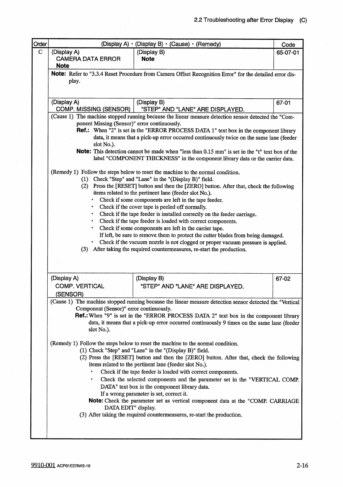
C
(
Display
A
)
CAMERA
DATA
ERROR
(
Display
B
)
Note
65
-
07
-
01
Note
Note
:
Refer
to
,
f
3.3
.
4
Reset
Procedure
from
Camera
Offset
Recognition
Error
”
for
the
detailed
error
dis
-
play
.
(
Display
A
)
COMP
.
MISSING
(
SENSOR
)
"
STEP
"
AND
"
LANE
"
ARE
DISPLAYED
.
(
Display
B
)
67
-
01
(
Cause
1
)
The
machine
stopped
running
because
the
linear
measure
detection
sensor
detected
the
M
Com
-
ponent
Missing
(
Sensor
)
"
error
continuously
.
Ref
.
:
When
n
2
M
is
set
in
the
”
ERROR
PROCESS
DATA
1
”
text
box
in
the
component
library
data
,
it
means
that
a
pick
-
up
error
occurred
continuously
twice
on
the
same
lane
(
feeder
slot
No
.
)
.
Note
:
This
detection
cannot
be
made
when
THICKNESS
i
"
less
than
0.15
mm
"
is
set
in
the
"
t
"
text
box
of
the
S
"
in
the
component
library
data
or
the
carrier
data
.
label
”
COMPONENT
(
Remedy
1
)
Follow
the
steps
below
to
reset
the
machine
to
the
normal
condition
.
(
1
)
Check
"
Step
"
and
”
Lane
”
in
the
"
(
Display
B
)
"
field
.
(
2
)
Press
the
e
[
RESET
]
button
and
then
the
[
ZERO
]
button
.
After
that
,
lated
to
the
pertinent
lane
(
feeder
slot
No
.
)
.
check
the
following
items
re
•
Check
if
some
components
are
left
in
the
tape
feeder
.
•
Check
if
the
cover
tape
is
peeled
off
normally
.
•
Check
if
the
tape
feeder
is
installed
correctly
on
the
feeder
carriage
.
•
Check
if
the
tape
feeder
is
loaded
with
correct
components
.
•
Check
if
some
components
are
left
in
the
carrier
tape
.
If
left
,
be
sure
to
remove
them
to
protect
the
cutter
blades
from
being
damaged
.
•
Check
if
the
vacuum
nozzle
is
not
clogged
or
proper
vacuum
pressure
is
applied
.
(
3
)
After
taking
the
required
countermeasures
,
re
-
start
the
production
.
(
Display
A
)
COMP
.
VERTICAL
(
Display
B
)
"
STEP
"
AND
"
LANE
"
ARE
DISPLAYED
.
67
-
02
(
SENSOR
)
(
Cause
1
)
The
machine
stopped
running
because
the
linear
measure
detection
sensor
detected
the
"
Vertical
Component
(
Sensor
)
"
error
continuously
.
Ref
.
:
When
"
9
tf
is
set
in
the
"
ERROR
PROCESS
DATA
2
"
text
box
in
the
component
library
data
,
it
means
that
a
pick
-
up
error
occurred
continuously
9
times
on
the
same
lane
(
feeder
slot
No
.
)
.
(
Remedy
1
)
Follow
the
steps
below
to
reset
the
machine
to
the
normal
condition
.
(
1
)
Check
"
Step
"
and
"
Lane
"
in
the
"
(
Display
B
)
”
field
.
(
2
)
Press
the
[
RESET
]
button
and
then
the
[
ZERO
]
button
.
After
that
,
check
the
following
items
related
to
the
pertinent
lane
(
feeder
slot
No
.
)
.
•
Check
if
the
tape
feeder
is
loaded
with
correct
components
.
•
Check
the
selected
components
and
the
parameter
set
in
the
nVERTICAL
COMP
.
DATA
"
text
box
in
the
component
library
data
.
If
a
wrong
parameter
is
set
,
correct
it
.
Note
:
Check
the
parameter
set
as
vertical
component
data
at
the
nCOMP
.
CARRIAGE
DATAEDIT
”
display
.
(
3
)
After
taking
the
required
countermeasures
,
re
-
start
the
production
.
9910
-
001
ACP
01
EERW
2
-
16
2
-
16
2.2
Troubleshooting
after
Error
Display
(
C
)
Order
(
Display
A
)
•
(
Display
B
)
y
(
Cause
)
>
(
Remedy
)
Code
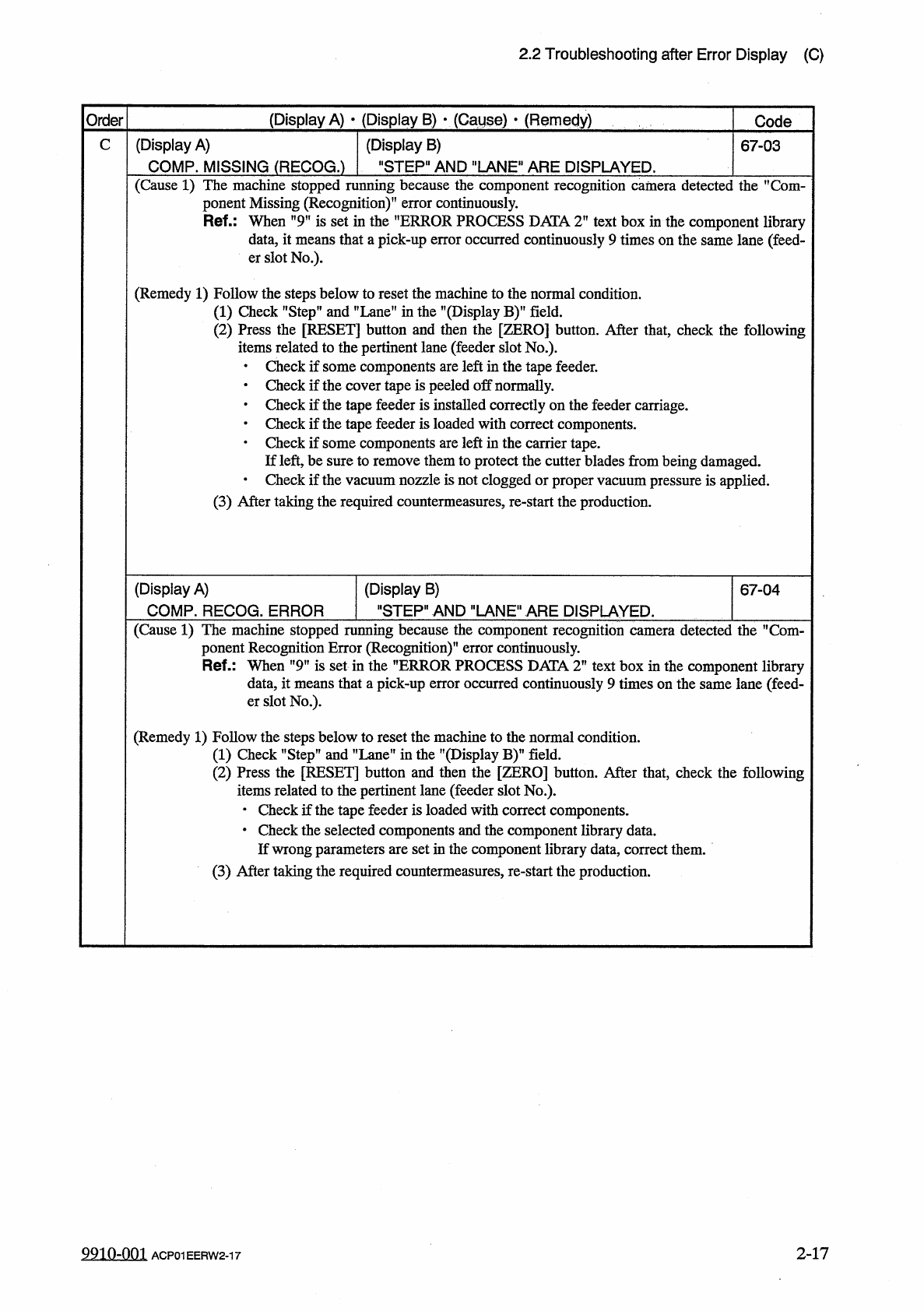
C
(
Display
A
)
COMP
.
MISSING
(
RECOG
.
)
(
Display
B
)
"
STEP
"
AND
"
LANE
"
ARE
DISPLAYED
.
67
-
03
(
Cause
1
)
The
machine
stopped
running
because
the
component
recognition
camera
detected
the
,
f
Com
-
ponent
Missing
(
Recognition
)
”
error
continuously
.
Ref
.
:
When
"
9
"
is
set
in
the
"
ERROR
PROCESS
DATA
T
text
box
in
the
component
library
data
,
it
means
that
a
pick
-
up
error
occurred
continuously
9
times
on
the
same
lane
(
feed
-
er
slot
No
.
)
.
(
Remedy
1
)
Follow
the
steps
below
to
reset
the
machine
to
the
normal
condition
.
(
1
)
Check
"
Step
”
and
”
Lane
"
in
the
"
(
Display
(
2
)
Press
the
[
RESET
]
button
and
then
the
[
items
related
to
the
pertinent
lane
(
feeder
slot
No
.
)
.
•
Check
if
some
components
are
left
in
the
tape
feeder
.
•
Check
if
the
cover
tape
is
peeled
off
normally
.
•
Check
if
the
tape
feeder
is
installed
correctly
on
the
feeder
carriage
.
•
Check
if
the
tape
feeder
is
loaded
with
correct
components
.
•
Check
if
some
components
are
left
in
the
carrier
tape
.
If
left
,
be
sure
to
remove
them
to
protect
the
cutter
blades
from
being
damaged
.
•
Check
if
the
vacuum
nozzle
is
not
clogged
or
proper
vacuum
pressure
is
applied
.
(
3
)
After
taking
the
required
countermeasures
,
re
-
start
the
production
.
BY
field
.
ZERO
]
button
.
After
that
,
check
the
following
(
Display
A
)
COMP
.
RECOG
.
ERROR
(
Display
B
)
"
STEP
"
AND
"
LANE
"
ARE
DISPLAYED
.
67
-
04
(
Cause
1
)
The
machine
stopped
running
because
the
component
recognition
camera
detected
the
M
Com
-
ponent
Recognition
Error
(
Recognition
)
"
error
continuously
.
Ref
.
:
When
"
9
”
is
set
in
the
”
ERROR
PROCESS
DATA
T
text
box
in
the
component
library
data
,
it
means
that
a
pick
-
up
error
occurred
continuously
9
times
on
the
same
lane
(
feed
-
er
slot
No
.
)
.
(
Remedy
1
)
Follow
the
steps
below
to
reset
the
machine
to
the
normal
condition
.
(
1
)
Check
"
Step
”
and
"
Lane
”
in
the
"
(
Display
B
)
(
2
)
Press
the
[
RESET
]
button
and
then
the
[
ZERO
]
button
.
After
that
,
check
the
following
items
related
to
the
pertinent
lane
(
feeder
slot
No
.
)
.
•
Check
if
the
tape
feeder
is
loaded
with
correct
components
.
•
Check
the
selected
components
and
the
component
library
data
.
If
wrong
parameters
are
set
in
the
component
library
data
,
correct
them
.
(
3
)
After
taking
the
required
countermeasures
,
re
-
start
the
production
.
field
.
2
-
17
9910
-
001
ACP
01
EERW
2
-
17