5TROUBLESHOOTING_.pdf - 第151页
4.3 Troubleshooting for Placement Errors 4.3 Troubleshooting for Placement Errors 4.3 . 1 Cause and Remedy of Placement Errors 4.3 . 1 - 1 Positional and Angular Deviations of Component Placement ( 1 ) Situational Grasp …
4.2
Troubleshooting
on
Pick
-
Up
Errors
4.2
.
3.3
Component
Recognition
Error
(
Corner
Detection
Error
)
1
•
Applicable
Components
1005
X
2
-
Arrayed
Resistance
Network
2
.
Contents
of
Deficiency
Component
recognition
errors
(
comer
detection
errors
)
occurred
by
0.3
%
.
3
.
Cause
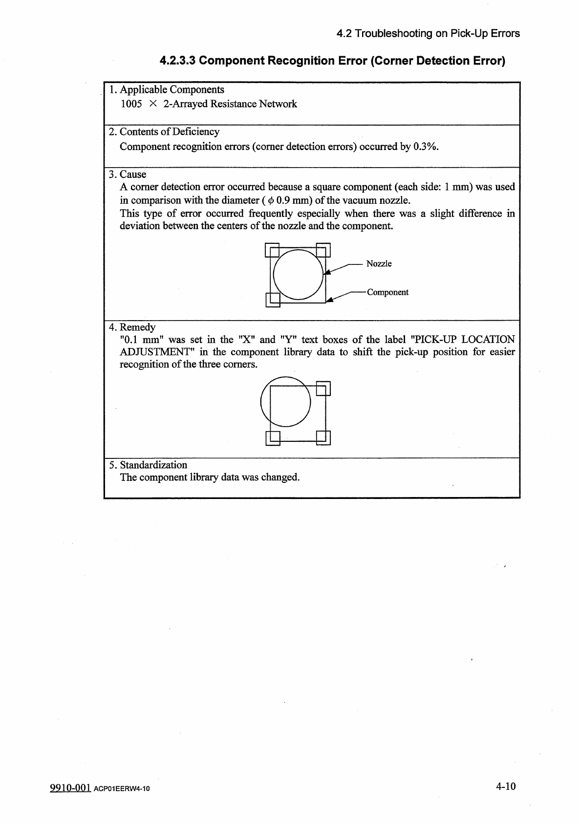
A
comer
detection
error
occurred
because
a
square
component
(
each
side
:
1
mm
)
was
used
in
comparison
with
the
diameter
(
0
0.9
mm
)
of
the
vacuum
nozzle
.
This
type
of
error
occurred
frequently
especially
when
there
was
a
slight
difference
in
deviation
between
the
centers
of
the
nozzle
and
the
component
.
4
.
Remedy
"
0.1
mm
"
was
set
in
the
"
X
"
and
"
Y
"
text
boxes
of
the
label
"
PICK
-
UP
LOCATION
ADJUSTMENT
*
'
in
the
component
library
data
to
shift
the
pick
-
up
position
for
easier
recognition
of
the
three
comers
.
a
E
y
]
5
.
Standardization
The
component
library
data
was
changed
.
4
-
10
9910
-
001
ACP
01
EERW
4
-
10
4.3
Troubleshooting
for
Placement
Errors
4.3
Troubleshooting
for
Placement
Errors
4.3
.
1
Cause
and
Remedy
of
Placement
Errors
4.3
.
1
-
1
Positional
and
Angular
Deviations
of
Component
Placement
(
1
)
Situational
Grasp
of
Error
Generation
Positional
and
angular
deviations
may
be
generated
in
either
Process
C
or
D
and
E
.
See
Fig
.
4.1
.
By
placing
a
component
on
the
P
.
C
.
B
.
where
a
double
-
faced
adhesive
tape
is
affixed
,
it
can
be
checked
and
determined
in
which
process
positional
and
angular
deviations
are
generated
.
When
a
positional
deviation
is
generated
on
the
double
-
faced
tape
,
it
indicates
that
positional
and
angular
deviations
occur
in
Process
C
.
When
no
positional
deviation
is
generated
,
it
means
that
positional
and
angular
deviations
occur
in
Process
D
or
E
.
(
2
)
Positional
and
Angular
Deviations
in
Process
C
When
a
positional
deviation
is
generated
due
to
the
movement
of
the
head
after
component
recognition
or
a
rotational
deviation
by
placement
angle
correction
,
the
deviation
may
be
caused
mainly
by
the
following
two
factors
.
①
Deterioration
of
Vacuum
Suction
Force
②
Vibration
or
Shock
during
Nozzle
(
Head
)
Movement
of
the
above
factors
exists
,
unstable
components
(
components
that
cannot
be
picked
up
in
stable
condition
)
such
as
those
shown
in
Fig
.
4.5
are
directly
affected
.
When
a
positional
deviation
is
generated
on
the
components
(
the
components
of
the
same
type
that
have
been
used
in
the
past
actual
production
)
,
check
for
the
factors
described
in
®
and
②
.
As
for
vacuum
suction
force
,
check
the
nozzle
and
the
vacuum
line
.
As
for
vibration
during
nozzle
movement
,
check
the
related
spots
in
the
range
of
Process
C
.
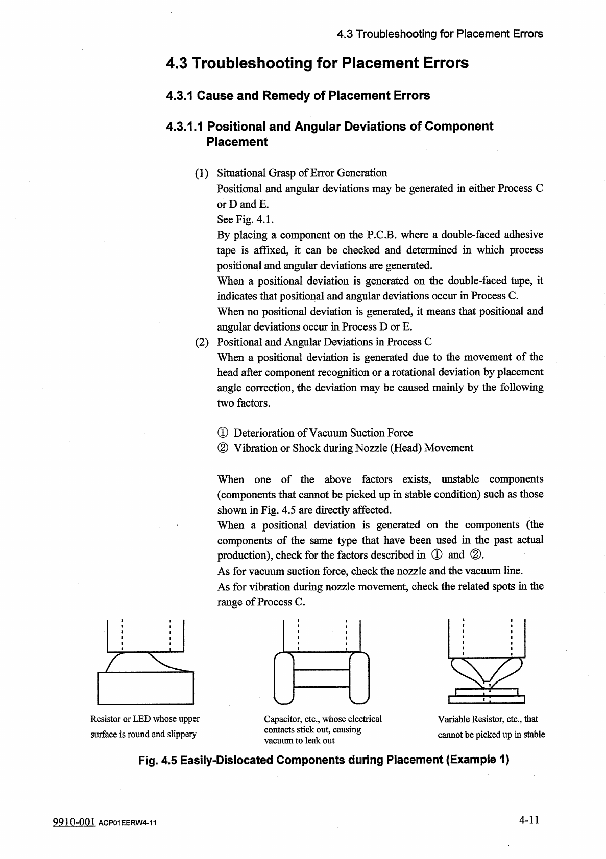
When
Resistor
or
LED
whose
upper
surface
is
round
and
slippery
Capacitor
,
etc
.
,
whose
electrical
contacts
stick
out
,
causing
vacuum
to
leak
out
Variable
Resistor
,
etc
.
,
that
cannot
be
picked
up
in
stable
Fig
.
4.5
Easily
-
Dislocated
Components
during
Placement
(
Example
1
)
4
-
11
9910
-
001
ACP
01
EERW
4
-
11
4.3
Troubleshooting
for
Placement
Errors
(
3
)
Positional
and
Angular
Deviations
in
Process
D
or
E
When
a
positional
deviation
is
not
generated
on
the
double
-
faced
adhesive
tape
,
it
indicates
that
positional
and
angular
deviations
occur
in
Process
D
or
E
.
As
a
phenomenon
at
this
time
®
The
component
is
dislocated
right
after
it
is
placed
.
②
The
component
is
dislocated
during
operation
subsequent
to
the
placement
.
③
The
component
is
dislocated
during
P
.
C
.
B
.
discharge
operation
subsequent
to
the
placement
.
The
causes
in
the
above
cases
lie
in
the
factors
affected
commonly
by
the
shape
of
the
component
,
the
condition
of
the
or
the
condition
of
cream
solder
or
glue
.
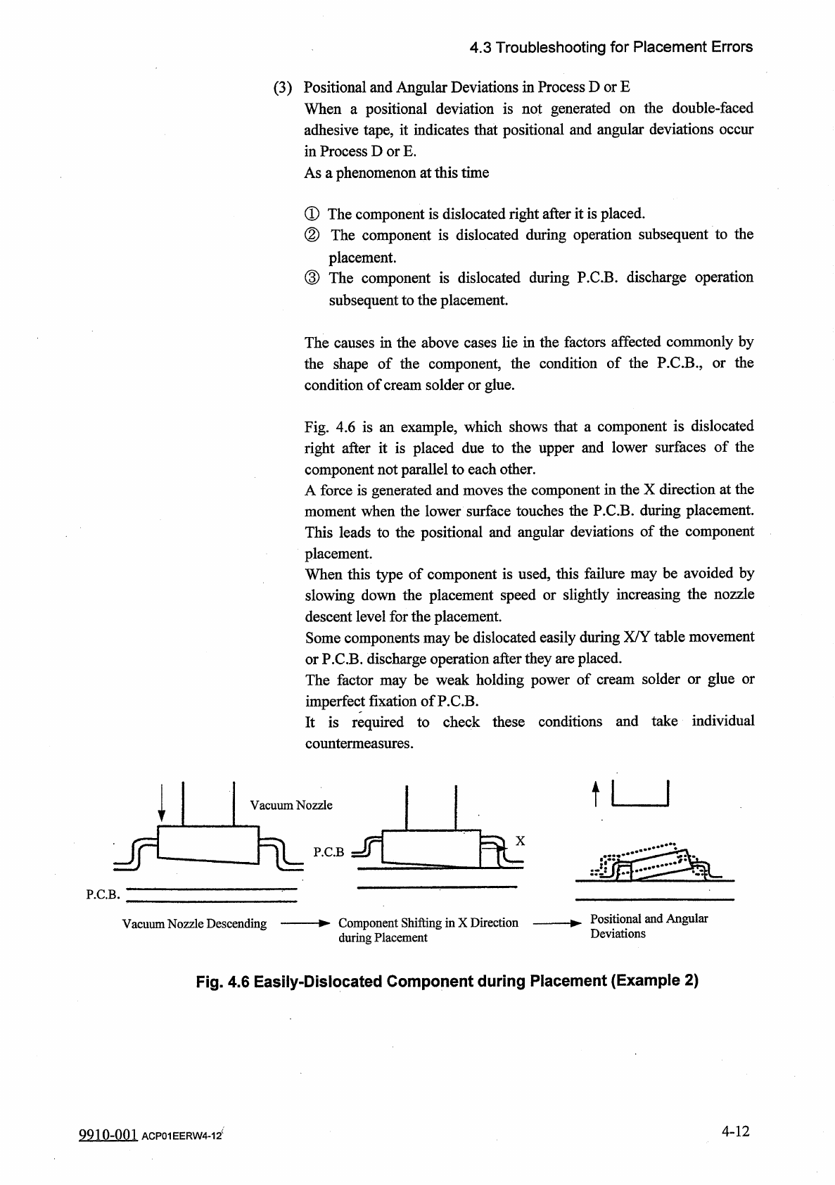
Fig
.
4.6
is
an
example
,
which
shows
that
a
component
is
dislocated
right
after
it
is
placed
due
to
the
upper
and
lower
surfaces
of
the
component
not
parallel
to
each
other
.
A
force
is
generated
and
moves
the
component
in
the
X
direction
at
the
moment
when
the
lower
surface
touches
the
P
.
C
.
B
.
during
placement
.
This
leads
to
the
positional
and
angular
deviations
of
the
component
placement
.
When
this
type
of
component
is
used
,
this
failure
may
be
avoided
by
slowing
down
the
placement
speed
or
slightly
increasing
the
nozzle
descent
level
for
the
placement
.
Some
components
may
be
dislocated
easily
during
X
/
Y
table
movement
or
P
.
C
.
B
.
discharge
operation
after
they
are
placed
.
The
factor
may
be
weak
holding
power
of
cream
solder
or
glue
or
imperfect
fixation
ofP
.
C
.
B
.
It
is
required
to
check
these
conditions
and
take
individual
countermeasures
.
个
l
Vacuum
Nozzle
Jr
P
.
C
.
B
P
.
C
.
B
.
Positional
and
Angular
Deviations
Vacuum
Nozzle
Descending
Component
Shifting
in
X
Direction
during
Placement
Fig
.
4.6
Easily
-
Dislocated
Component
during
Placement
(
Example
2
)
4
-
12
9910
-
001
ACP
01
EERW
4
-
12
c