5TROUBLESHOOTING_.pdf - 第95页
3.3 . 1 Reset Procedure from Component Recognition Error 3.3 Troubleshooting against Recognition Errors 3.3 . 1 Reset Procedure from Component Recognition Error Shown below are the contents of the error codes which are g…
3.2
Basic
System
of
Recognition
Error
Codes
3.2
Basic
System
of
Recognition
Error
Codes
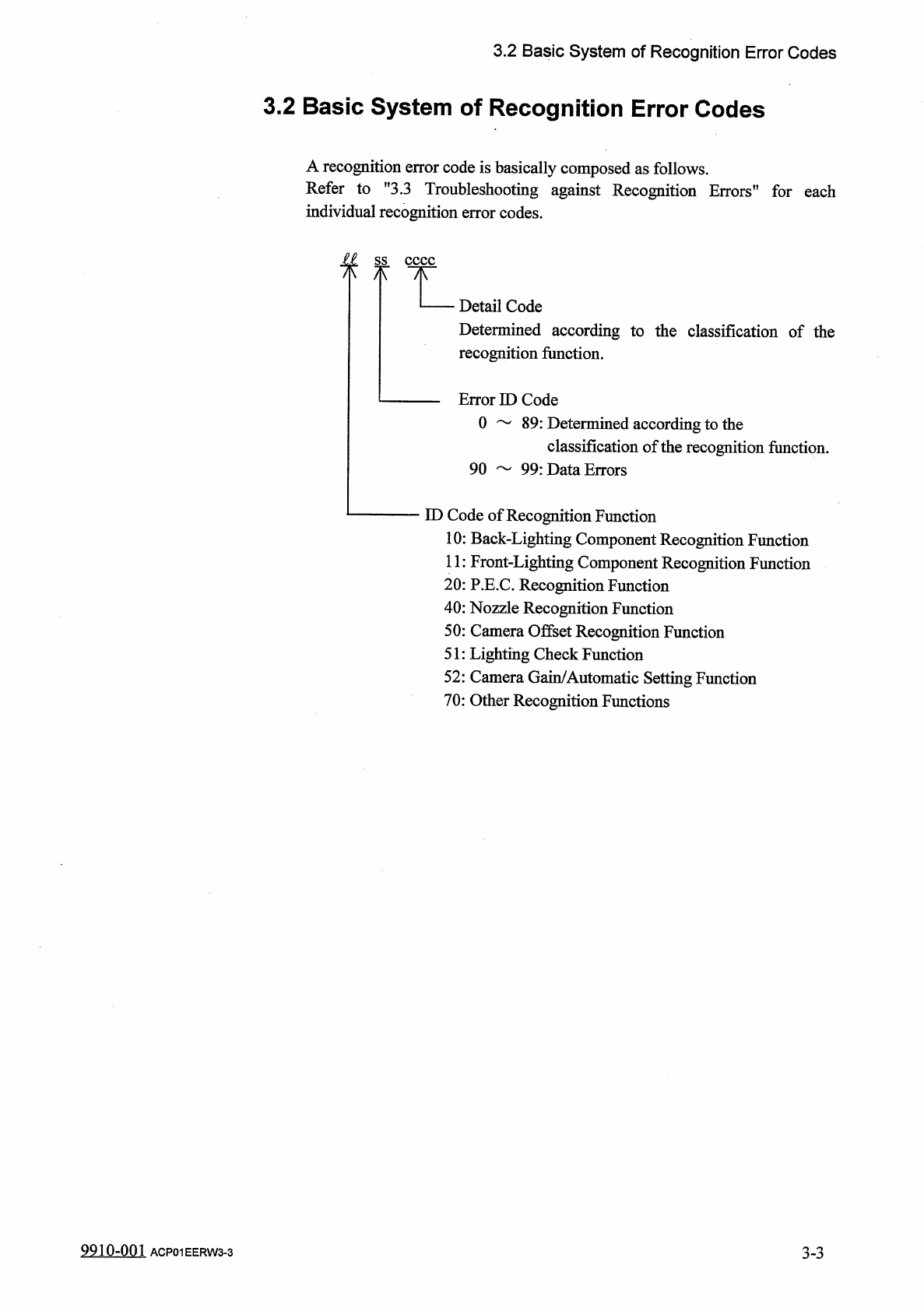
A
recognition
error
code
is
basically
composed
as
follows
.
Refer
to
,
f
3.3
Troubleshooting
against
Recognition
Errors
,
!
for
each
individual
recognition
error
codes
.
£
L
ss
八
Detail
Code
Determined
according
to
the
classification
of
the
recognition
function
.
Error
ID
Code
0
89
:
Determined
according
to
the
classification
of
the
recognition
function
.
90
99
:
Data
Errors
ID
Code
of
Recognition
Function
10
:
Back
-
Lighting
Component
Recognition
Function
11
:
Front
-
Lighting
Component
Recognition
Function
20
:
P
.
E
.
C
.
Recognition
Function
40
:
Nozzle
Recognition
Function
50
:
Camera
Offset
Recognition
Function
51
:
Lighting
Check
Function
52
:
Camera
Gain
/
Automatic
Setting
Function
70
:
Other
Recognition
Functions
3
-
3
9910
-
001
ACP
01
EERW
3
-
3
3.3
.
1
Reset
Procedure
from
Component
Recognition
Error
3.3
Troubleshooting
against
Recognition
Errors
3.3
.
1
Reset
Procedure
from
Component
Recognition
Error
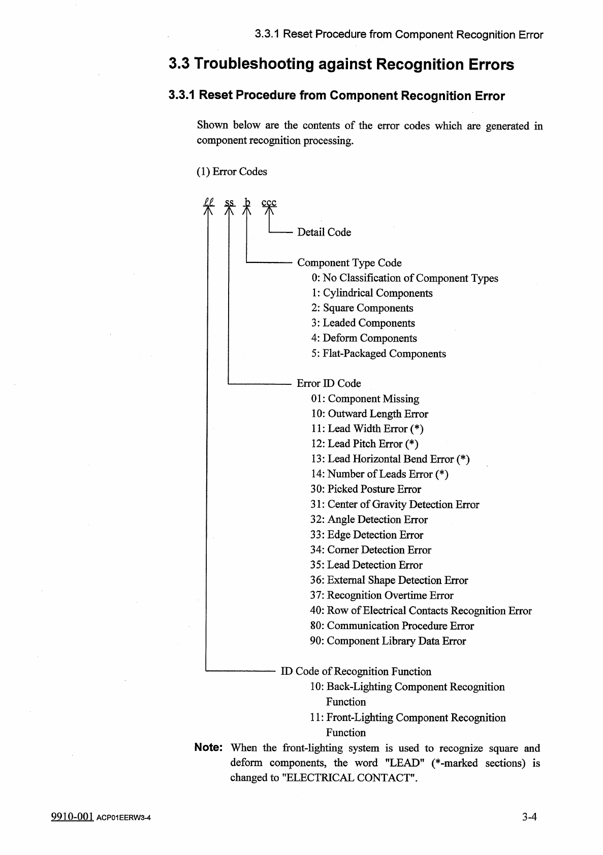
Shown
below
are
the
contents
of
the
error
codes
which
are
generated
in
component
recognition
processing
.
(
1
)
Error
Codes
£
1
ss
,
h
八 八 八
Detail
Code
Component
Type
Code
0
:
No
Classification
of
Component
Types
1
:
Cylindrical
Components
2
:
Square
Components
3
:
Leaded
Components
4
:
Deform
Components
5
:
Flat
-
Packaged
Components
Error
ID
Code
01
:
Component
Missing
10
:
Outward
Length
Error
11
:
Lead
Width
Error
(
*
)
12
:
Lead
Pitch
Error
(
*
)
13
:
Lead
Horizontal
Bend
Error
(
*
)
14
:
Number
of
Leads
Error
(
*
)
30
:
Picked
Posture
Error
31
:
Center
of
Gravity
Detection
Error
32
:
Angle
Detection
Error
33
:
Edge
Detection
Error
34
:
Comer
Detection
Error
35
:
Lead
Detection
Error
36
:
External
Shape
Detection
Error
37
:
Recognition
Overtime
Error
40
:
Row
of
Electrical
Contacts
Recognition
Error
80
:
Communication
Procedure
Error
90
:
Component
Library
Data
Error
ID
Code
of
Recognition
Function
10
:
Back
-
Lighting
Component
Recognition
Function
11
:
Front
-
Lighting
Component
Recognition
Function
Note
:
When
the
front
-
lighting
system
is
used
to
recognize
square
and
deform
components
,
the
word
"
LEAD
"
(
*
-
marked
sections
)
is
changed
to
"
ELECTRICAL
CONTACT
"
.
3
-
4
9910
-
001
ACP
01
EERW
3
-
4
3.3
.
1
Reset
Procedure
from
Component
Recognition
Error
(
1
L
01
)
•
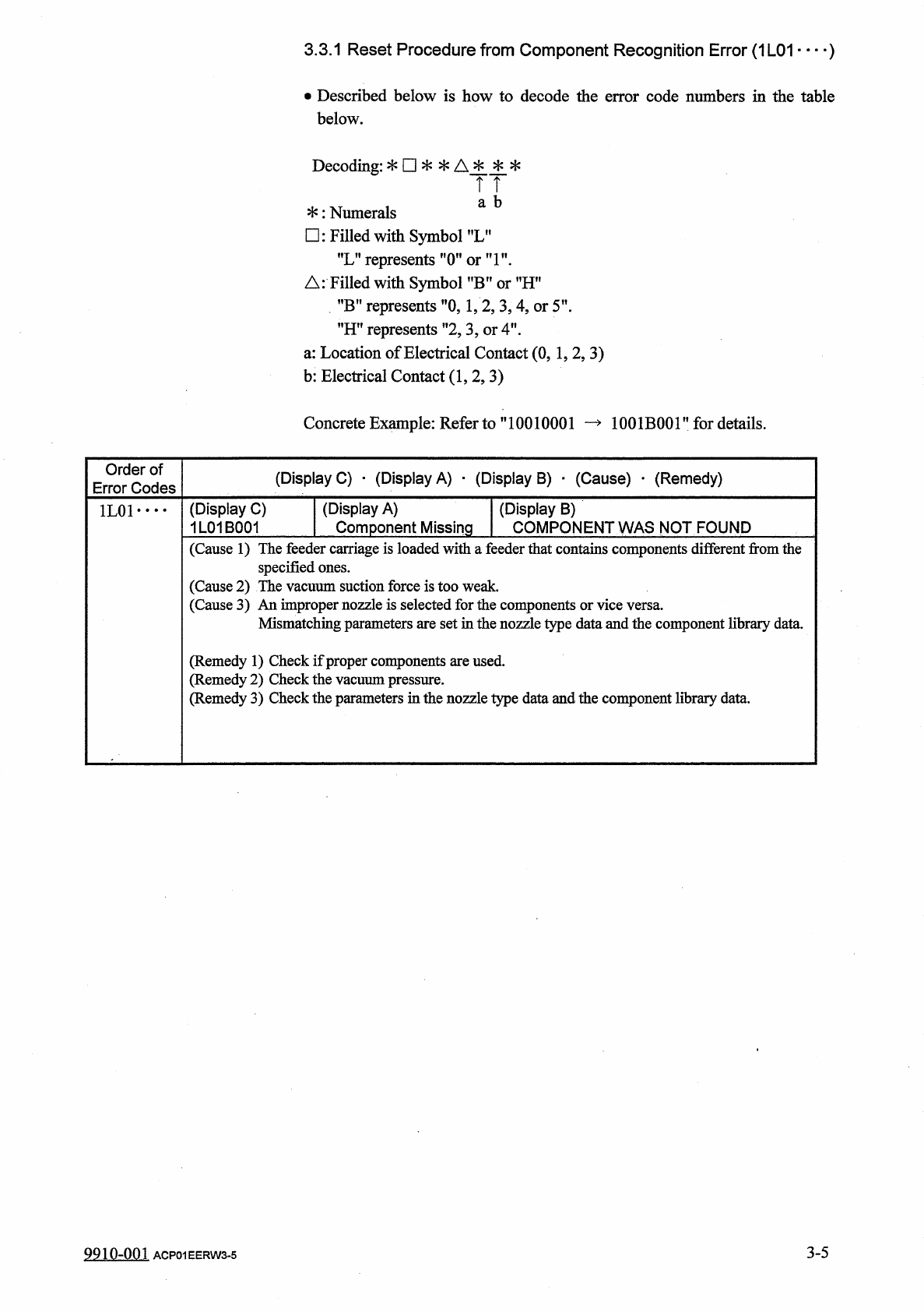
Described
below
is
how
to
decode
the
error
code
numbers
in
the
table
below
.
Decoding
:
*
□
*
*
A
*
*
*
TT
a
b
*
:
Numerals
□
:
Filled
with
Symbol
f
,
LM
"
L
”
represents
"
(
Tori
"
.
△
:
Filled
with
Symbol
?
,
B
,
?
or
MHn
”
B
”
represents
"
0
,
1
,
2
,
3
,
4
,
or
5
'
"
H
"
represents
”
2
,
3
,
or
4
"
.
a
:
Location
of
Electrical
Contact
(
0
,
1
,
2
,
3
)
b
:
Electrical
Contact
(
1
,
2
,
3
)
Concrete
Example
:
Refer
to
”
10010001
—
1001
B
001
”
for
details
.
Order
of
Error
Codes
(
Display
C
)
•
(
Display
A
)
■
(
Display
B
)
■
(
Cause
)
_
(
Remedy
)
(
Display
A
)
Component
Missing
(
Display
C
)
1
L
01
B
001
(
Display
B
)
COMPONENT
WAS
NOT
FOUND
1
L
01
• •
•
•
(
Cause
1
)
The
feeder
carriage
is
loaded
with
a
feeder
that
contains
components
different
from
the
specified
ones
.
(
Cause
2
)
The
vacuum
suction
force
is
too
weak
.
(
Cause
3
)
An
improper
nozzle
is
selected
for
the
components
Mismatching
parameters
are
set
in
the
nozzle
type
data
and
the
component
library
data
.
(
Remedy
1
)
Check
if
proper
components
are
used
,
edy
2
)
Check
the
vacuum
pressure
.
edy
3
)
Check
the
parameters
in
the
nozzle
type
data
and
the
component
library
data
.
(
Remi
(
Remi
3
-
5
9910
-
001
ACP
01
EERW
3
-
5