YG200_YG200L_Mainte_E.pdf - 第70页
3-30 3 Periodic maintenance items 5 R e m ov e t h e c a m p i n a n d c a m . 1 . U s e t w e e z e r s o r s i m i l a r p o i n t e d t o o l t o p u s h t h e c a m p i n f r o m t h e e n d w h e r e t h e E - r i n…
3-29
3
Periodic maintenance items
3.3 FNC lock pin
Inside the spline shaft of each FNC head ("F" type heads 2, 4 and 6), a lock pin (or locate pin) is used to lock
the rotation of the FNC nozzle assembly when the selected nozzle points downwards. If dust or grime adheres
to this lock pin, the R-axis spline belt might skip teeth or component pick-and-place errors might occur.
Although depending on the operation time, clean the FNC lock pin once a year. Follow the procedure below to
clean the FNC lock pin.
3.3.1 Removing FNC lock pin
1
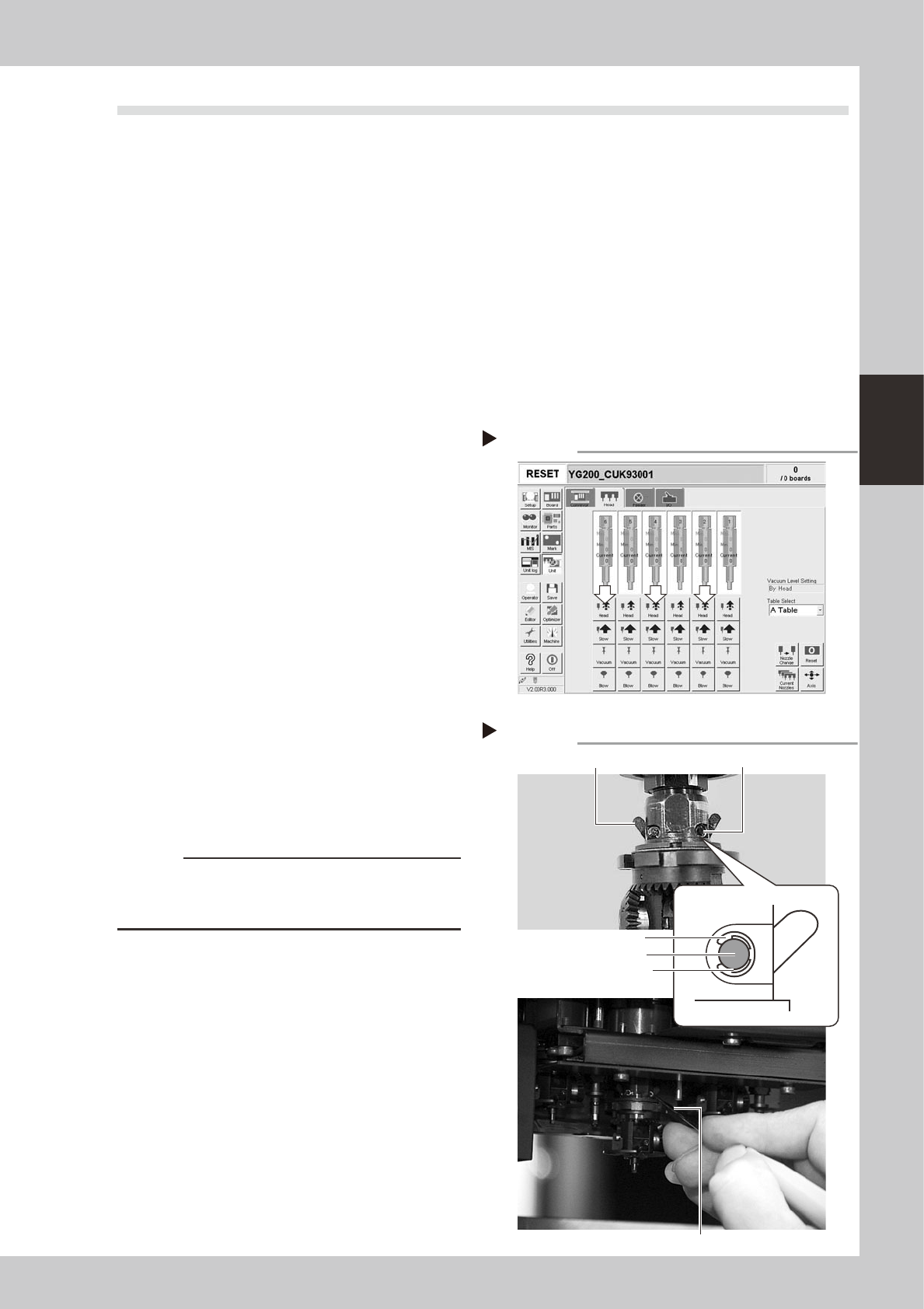
Select "Type 202F nozzle" for the
FNC heads.
On the [Unit]-[Head] tab screen, press the
[Nozzle Change] button and select
"Type-202" for the FNC heads (Heads 2, 4
and 6).
2
Press the emergency stop button.
e
The machine must be in emergency stop for
safe maintenance work.
3
Lower the spline shaft of the FNC
head.
On the [Unit]-[Head] tab screen, press the
[Head] button to lower the head. Two small
cams located just above the bevel gear
appear. (These cams move as the FNC lock
pin inside the spline shaft moves.)
54301-F8-00
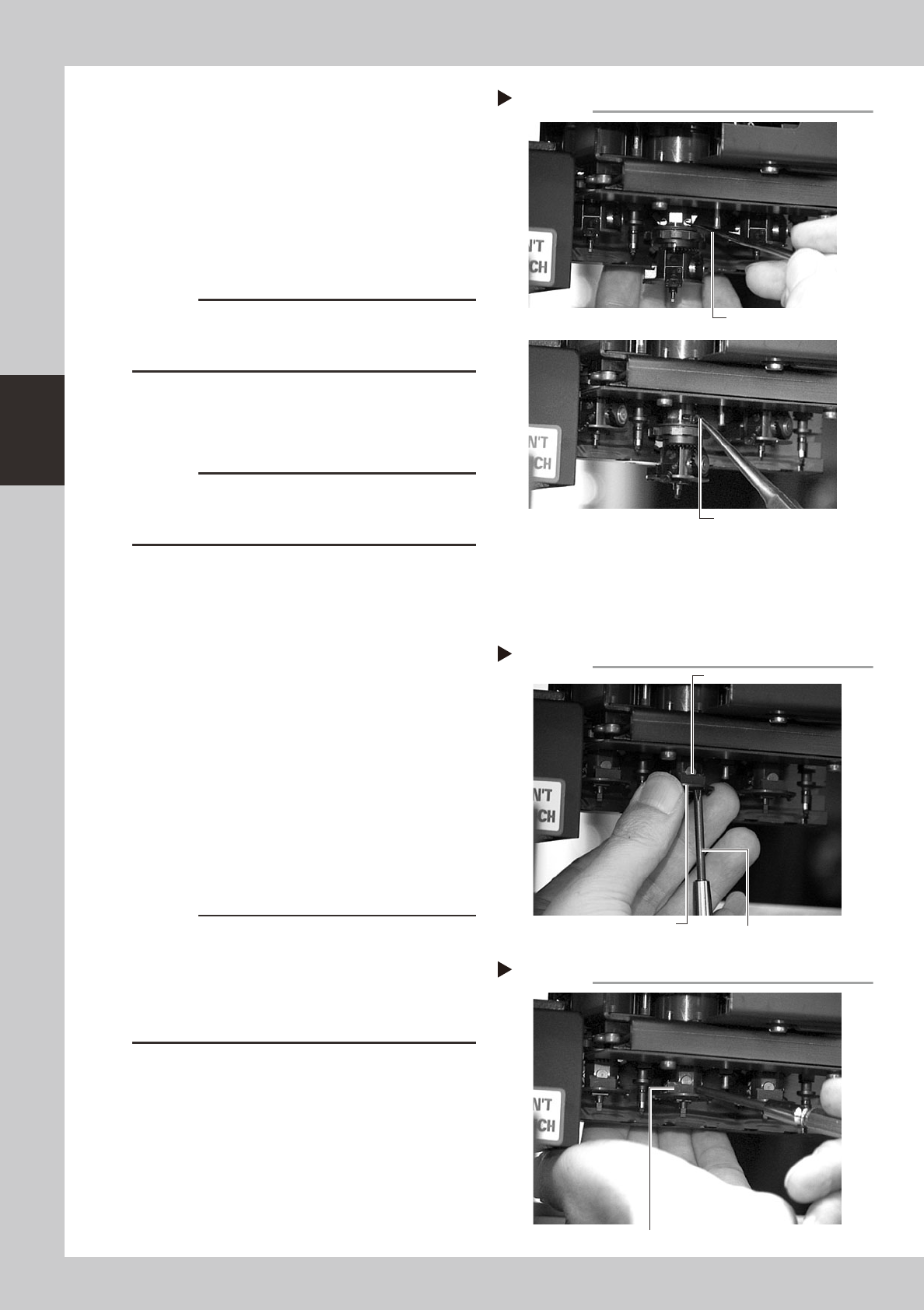
4
Remove the E-rings that fasten the
cam pins.
1. Rotate the R-axis belt so that the spline
shaft is positioned where the E-ring can
be easily removed.
2. Insert the E-ring remover into the gap
between the E-ring and the cam pin,
and pry it to remove the E-ring. (There
are two E-rings for each FNC head.)
53346-F8-00
c
CAUTION
Use caution when removing the E-ring so that it won't fly
out. The E-ring once removed cannot be reused.
Always use a new E-ring for reassembly.
[Head] up/down button
Step 3
246
Removing the E-ring
Step 4
Cam
E-ring
E-ring remover
Insert the E-ring remover between
E-ring and pin to remove E-ring.
Cam Cam pin
3-30
3
Periodic maintenance items
5
Remove the cam pin and cam.
1. Use tweezers or similar pointed tool to
push the cam pin from the end where
the E-ring was removed.
2. Pinch the opposite end of the pin cam
and pull it out from the index holder.
3. When the cam still stays in the index
holder, remove it with finger or tweezers.
53347-F8-00
c
CAUTION
When pulling out the cam pin in substep 2, the cam
may drop down, so place your palm under the spline
shaft.
6
Remove the other cam.
Use the same procedure in steps 5 and 6 to
remove E-ring, cam pin and cam.
c
CAUTION
The cams and cam pins are very small. Be careful not
to lose them during work. We recommend you prepare
spare parts.
7
Remove the black seal (KV8-
M71RH-00X) on the bottom of the
FNC head.
A black seal is affixed to the bottom of each
FNC head (Heads 2, 4 and 6) to cover the
screws that secure the stopper block.
Remove this black seal to loosen the screws
in the next step.
8
Remove the stopper block.
1. Use the Phillips screwdriver to remove the
two screws securing the stopper block to
the FNC head from the bottom.
2. Remove the stopper block by sliding it
out.
53348-F8-00
53349-F8-00
c
CAUTION
• When loosening the stopper block screws, hold the
edge of the FNC assembly so it won't rotate.
The spline belt might otherwise slip on the gear teeth.
• The screwdriver bit size might slightly differ between
manufacturers. Use the screwdriver that matches the
recessed pattern on the screw head.
Removing the cam pin.
Step 5
Push in the cam.
Pull out the cam.
Removing the stopper block
Step 8-1
Phillips screwdriver
Loose the screw
while holding this edge.
Stopper block
Removing the stopper block
Step 8-2
Slide out the stopper block by pushing it with a fingertip.
3-31
3
Periodic maintenance items
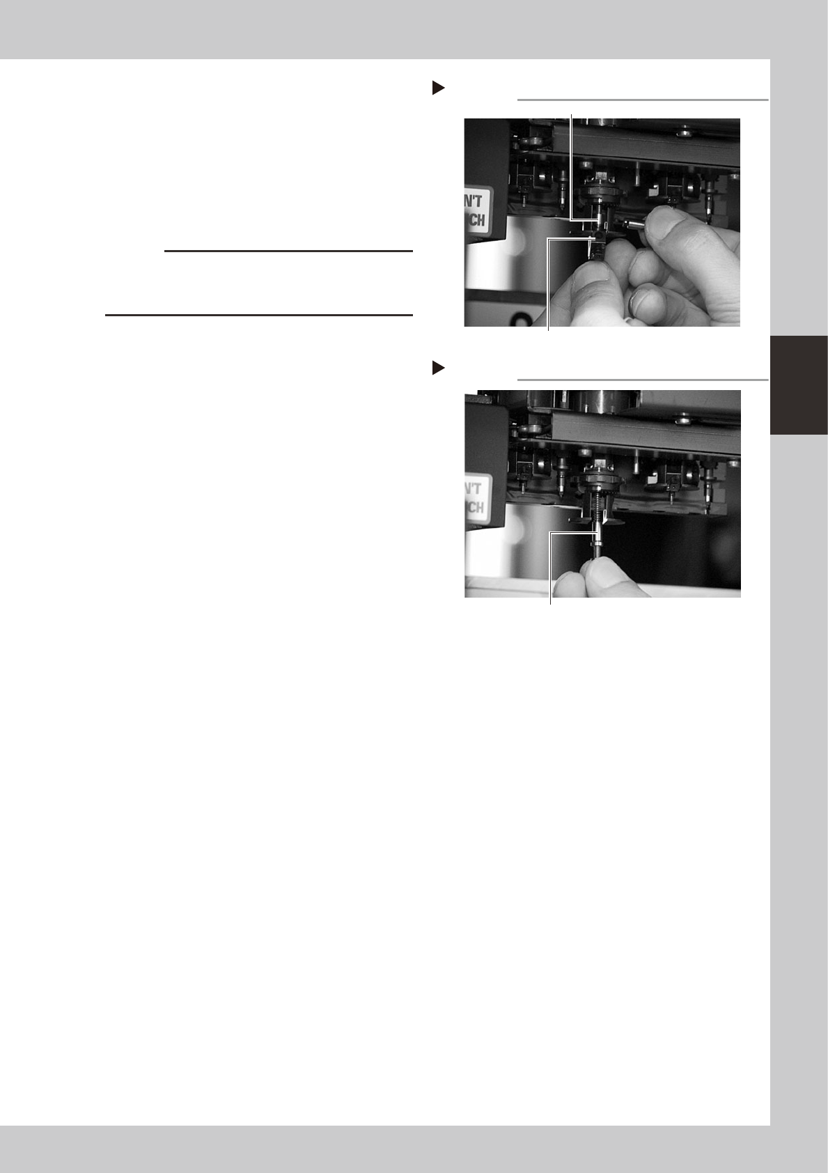
9
Remove the FNC nozzle assembly.
While gripping the nozzle assembly, pull out
the FNC nozzle shaft horizontally along with
the bevel gear and remove the nozzle
assembly by pulling it down.
The FNC lock pin and spring inside the spline
shaft may slide down at this point, so be
careful not to lose them.
53350-F8-00
c
CAUTION
Do not mix up the nozzle assemblies, bevel gears and
shafts of the different heads. Keep them as the original
set for each FNC head.
0
Take out the FNC lock pin and
spring.
When the FNC lock pin and spring still remain
in the spline shaft, pull them out down.
53351-F8-00
Removing the FNC nozzle assembly
Step 9
FNC lock pin
FNC nozzle assembly
Removing the lock pin and spring
Step 10
Take out the FNC lock pin and spring.