YG200_YG200L_Mainte_E.pdf - 第83页
4-6 4 How to replace consumable parts 5 . C o n v e y o r b e l t 1 Pr e s s t h e e m e r g e n c y s t o p b u t t o n . e T h e m a c h i n e m u s t b e i n e m e r g e n c y s t o p t o e n s u r e s a f e t y d u r…
4-5
4
How to replace consumable parts
4. Feeder valves
1
Turn off the machine power switch.
Quit the application software (VGOS) and
turn off the machine power switch by turning
it to the left.
2
Shut off the air supply.
Open the lower left cover on the front of the
machine and tune the air supply/shutoff
switch to the left to cut off the air supply.
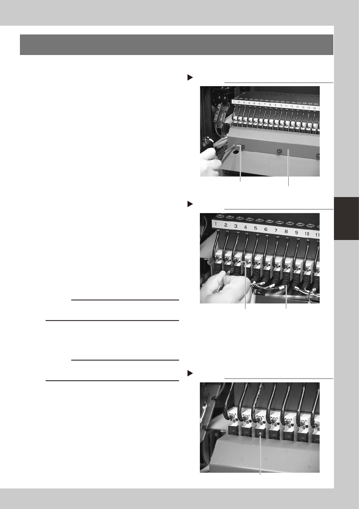
3
Remove the wire harness cover.
Use a Phillips screwdriver to loosen and
remove the screws that secure the wire
harness cover to the machine body.
53408-F8-00
4
Remove the feeder valve.
1. Detach the connector from the feeder
valve to be replaced.
2. Use a precision screwdriver to loosen the
two screws and remove the feeder valve.
53409-F8-00
5
Remove the air hose.
Use a cutter to cut off the air hose and
remove it.
6
Attach a new feeder valve and the
wire harness cover.
Assemble the new feeder valve and wire
harness cover in the reverse order of steps 3
and 4.
c
CAUTION
Do not forget to fit the gasket in place. Use caution not
to fit the gasket inside-out or to pinch it.
7
Supply air to the machine.
Turn the air supply/shutoff switch back to the
right to supply air.
c
CAUTION
Always use the air hose supplied along with the air
valves.
8
Check the ejector operation.
1. Turn on the machine.
2. Install a feeder at the new feeder valve
position.
3. Open the [Unit]-[Feeder] tab screen and
check the feeder on/off operation.
53410-F8-00
Removing the wire harness cover
Step 3
Wire harness cover
Remove the screws
at both ends.
Removing the feeder valve
Step 4
Valve connector
Loosen these
two screws.
Checking the feeder valve operation
Step 8
LED lamp
4-6
4
How to replace consumable parts
5. Conveyor belt
1
Press the emergency stop button.
e
The machine must be in emergency stop to
ensure safety during work.
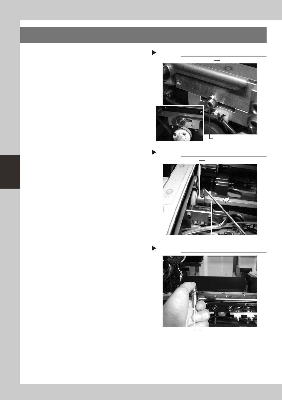
2
Mark the original position of the
belt tension adjustment bolt.
Put a mark at the original position of the belt
tension adjustment bolt before removing the
bolt.
53411-F8-00
3
Slacken the conveyor belt.
Loosen the belt tension adjustment bolt with
the M4 hex wrench and slide the bolt to the
right end (to the outer side of the machine)
along the slot hole.
53412-F8-00
4
Detach the conveyor belt from the
conveyor.
Use the M3 hex wrench to loosen the bolt
securing the drive pulley and pull out the
shaft. Then detach the belt from the pulley
and take it out through the space between
the pulley and the shaft.
53413-F8-00
5
Clean the conveyor rail.
Use a brush or air blow gun (with weak air
blow) to clean the gap between the
conveyor rail and PCB guide.
6
Attach a new conveyor belt.
1. Temporarily fit a new belt onto the pulley.
2. Reconnect the shaft to the pulley and
tighten the bolt.
3. Move the belt tension adjustment bolt to
the original position where you put a
mark and then tighten the bolt securely.
7
Check the belt rotating condition.
1. Open the [Unit]-[Conveyor] tab screen,
and turn on the conveyor motor with the
conveyor drive button. Then check the
belt rotation.
2. If the rotation speed fluctuates or there is
slack in the belt, adjust the position of
the tension adjustment bolt and then
check the rotation again.
Loosening the belt tension adjustment bolt
Step 3
Marking
Loosen this bolt.
Removing the shaft
Step 4
Shaft
Drive pulley
Cleaning the conveyor rail
Step 5
Air blow gun
4-7
4
How to replace consumable parts
6. Head up/down air valves
If a particular head does not move smoothly or does not operate at a slow speed even after selecting the
slow speed, the head up/down air valve or the head speed switching valve may be defective. If a head up/
down air valve is found to be defective, replace it as explained below.
6.1 Replacing the head up/down air valve
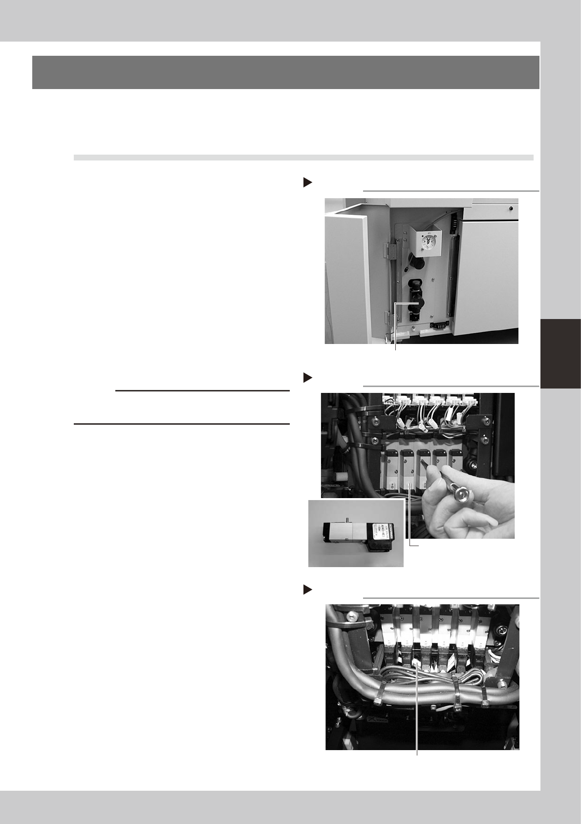
1
Shut off the air supply and turn off
the machine.
Turn the air supply/shutoff switch to the right
to cut off the air supply, quit the software,
and turn off the machine power switch.
53414-F8-00
2
Unplug the connector.
Unplug the connector of the head up/down
air valve to be replaced.
3
Remove the head up/down air
valve.
Use the Phillips screwdriver to loosen the two
screws securing the head up/down air valve,
and remove the head up/down air valve.
53415-F8-00
c
CAUTION
Be careful not to lose the O-ring and packing placed
between the head up/down air valve and manifold.
4
Attach a new head up/down air
valve.
1. Fit the O-ring and packing into the
manifold.
2. Pass the two screws through the new air
valve and tighten them into the manifold
with the Phillips precision screwdriver.
53416-F8-00
5
Attach the connector.
Plug the connector of the new air valve into
the mating socket.
6
Check operation status.
Supply air to the machine and turn on the
power switch. Open the [Unit]-[Head] tab
screen, press the [Head] button several
times, and check that the head lowers and
rises smoothly.
Shutting off the air supply
Step 1
Air supply/shutoff switch
Removing the connector and valve
Step 2,3
Head up/down valve
Attaching a new head up/down valve
Step 4
Connector