YG200_YG200L_Mainte_E.pdf - 第86页
4-9 4 How to replace consumable parts 7 R e p l a c e t h e s l o w - s p e e d v a l v e . 1 . U s e t h e P h i l l i p s p r e c i s i o n s c r e w d r i v e r t o l o o s e n a n d r e m o v e t h e t w o s c r e w …
4-8
4
How to replace consumable parts
6.2 Replacing the slow-speed valve
If a slow-speed valve (head up/down speed switching valve) is found to be defective, replace it as follows.
1
Shut off the air supply and turn off
the machine.
Turn the air supply/shutoff switch to the right
to cut off the air supply, quit the software,
and turn off the machine power switch.
2
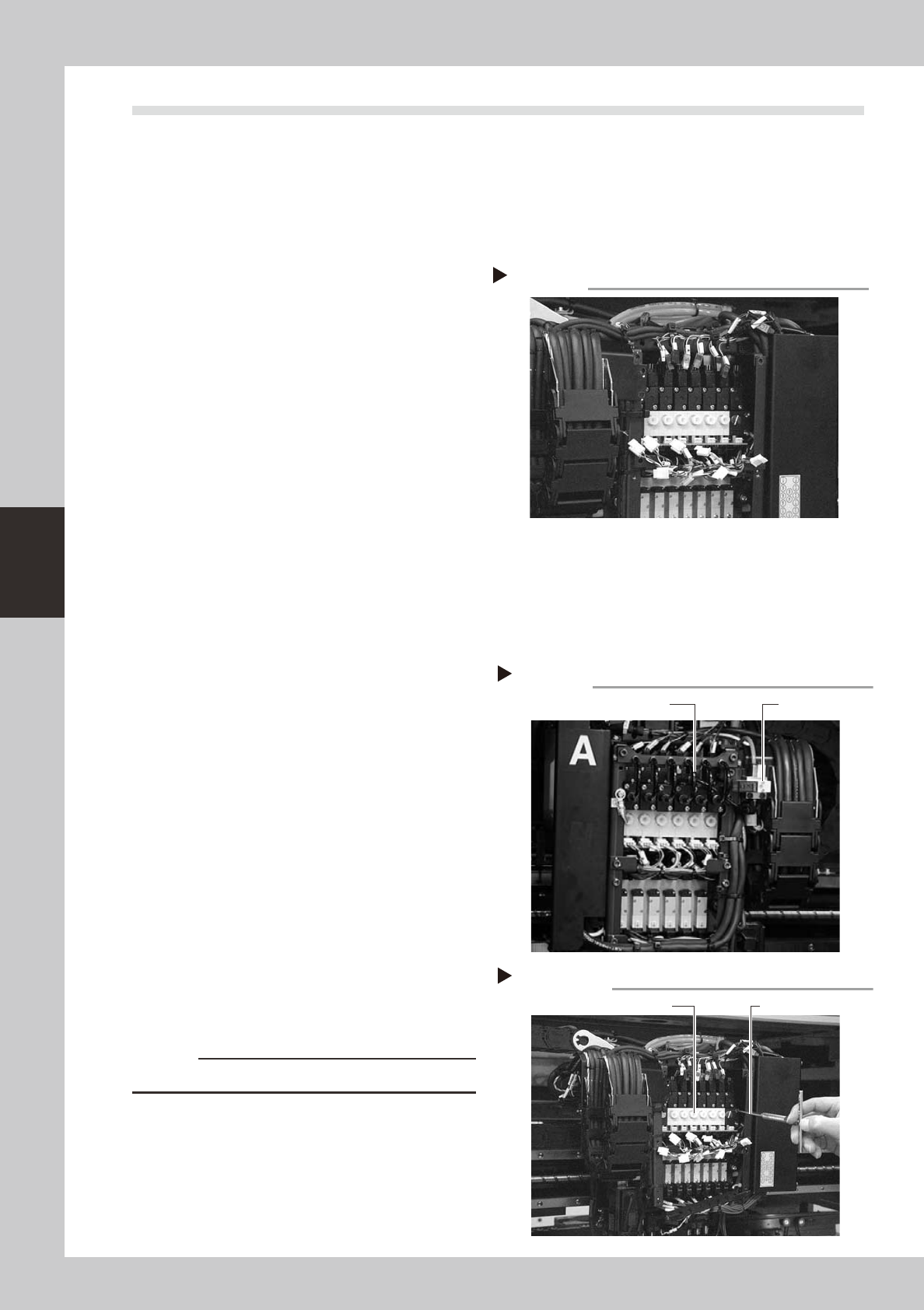
Unplug the connectors.
Unplug all connectors to the vacuum ejector
air valves, head up/down air valves, vacuum
sensors and the ground wire.
3
Disconnect the air tubes.
1. Disconnect all air tubes from the air joints
connected to the vacuum ejector valves
and head up/down air valves.
2. Use the Phillips screwdriver to remove the
ground wire connected to the cover
frame.
53417-F8-00
4
Remove the head down sensor stay.
Use the M3 hex wrench to loosen the two
bolts securing the stay and remove it from
the head assembly.
5
Remove the bolts on the upper
frame of the head assembly.
1. Remove the bolts on the upper frame of
the head assembly.
2. Loosen the M3 bolt on the lower part of
the head assembly I/O cover.
3. Unplug the connectors of the harness
wires coming from the I/O board and pull
the upper frame towards you.
4. Disconnect the air hose for shaft blow.
(YG200L only)
5. Use the hex wrench to remove the
manifold for the shaft blow valve. (YG200L
only)
53400-F4-00
6
Remove the ejector valve unit.
Use the M3 hex wrench to loosen the four
bolts securing the ejector valve unit and
remove it from the head assembly.
53418-F8-00
c
CAUTION
Be careful not to lose the O-rings.
Removing the manifold and air hose
Step 5-4,5
Air hose for shaft blow Manifold
Removing the ejector unit
Step 6
Ejector unit
M2.5 hex wrench
Unplugging the connectors
Step 2
4-9
4
How to replace consumable parts
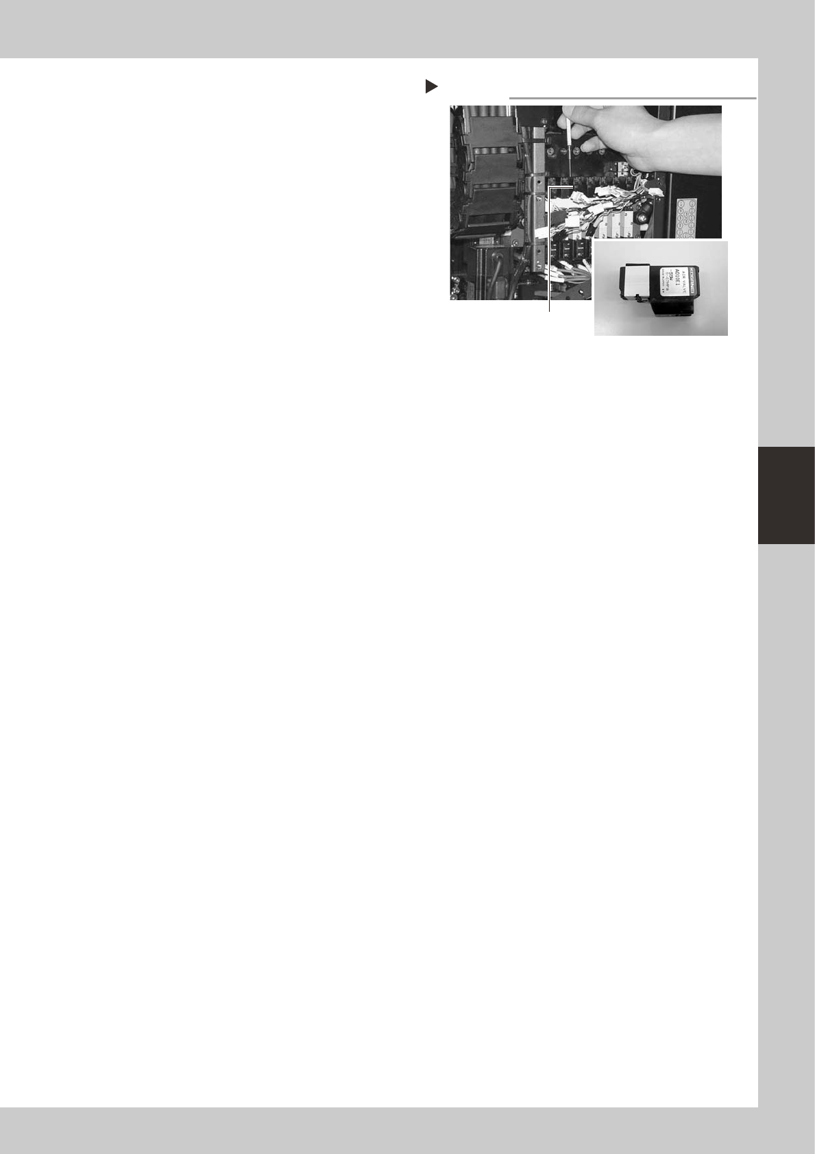
7
Replace the slow-speed valve.
1. Use the Phillips precision screwdriver to
loosen and remove the two screws
securing the slow-speed valve to be
replaced.
2. Attach a new slow-speed valve.
53419-F8-00
8
Reassemble all parts.
Attach the ejector air valve unit, connectors
and cover frame back to the original
positions, in the reverse procedure of steps 2
to 6.
9
Check operation status.
Supply air to the machine and turn on the
power switch. Open the [Unit]-[Head] tab
screen, press the [Slow] button, and press
the [Head] button several times to check
that the head lowers and rises smoothly at
the correct speed.
Removing the slow-speed valve
Step 7
Slow-speed valve

MAINTENANCE MANUAL
Nov. 2006
Version 2.00
© YAMAHA MOTOR CO., LTD. IM Operations
All rights reserved. No part of this publication may be
reproduced in any form without the permission of
YAMAHA MOTOR CO., LTD.
Information furnished by YAMAHA in this manual is believed to
be reliable. However, no responsibility is assumed for possible
inaccuracies or omissions. If you find any part unclear in this manual,
please contact YAMAHA or YAMAHA sales representatives.
,