YG200_YG200L_Mainte_E.pdf - 第73页
3-33 3 Periodic maintenance items 4 R e a t t a c h t h e F N C l o c k p i n a n d n o z z l e a s s e m b l y . 1 . I n s e r t t h e F N C l o c k p i n a n d s p r i n g i n t o t h e s p l i n e s h a f t . 2 . W i …
3-32
3
Periodic maintenance items
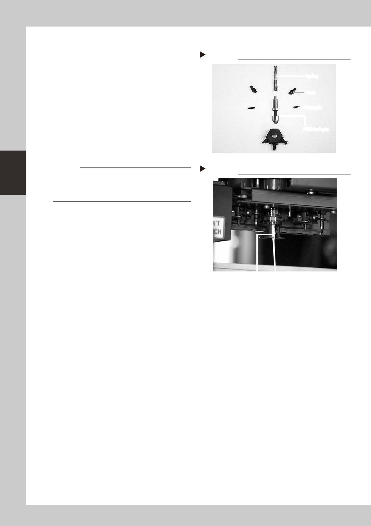
3.3.2 Cleaning and reassembling the FNC lock pin
1
Clean the FNC lock pin parts.
Use a cloth moistened with alcohol to wipe
the FNC lock pin, spring, cams and cam
pins.
53352-F8-00
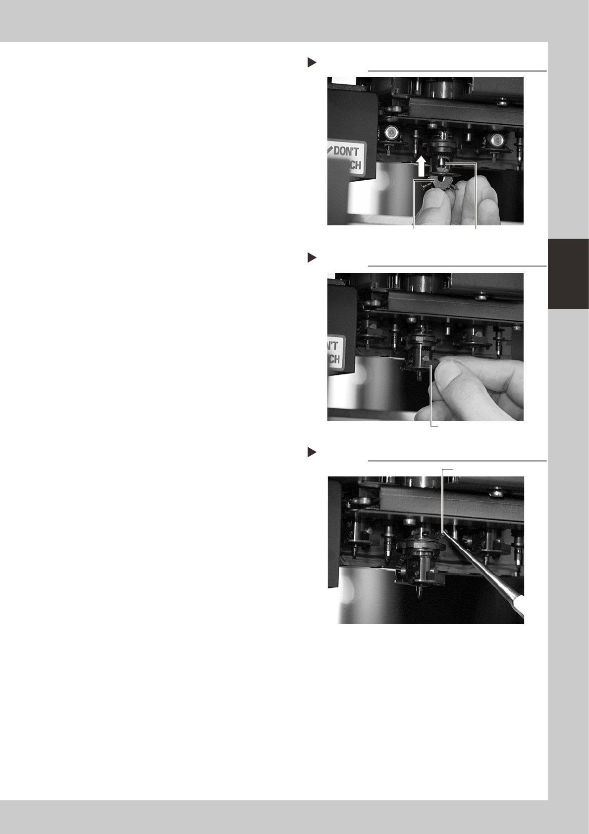
2
Clean the FNC lock pin insertion
section.
1. Blow air into the air path of the FNC lock
pin insertion section of the spline shaft.
2. Use a lint-free cotton swab, moistened
with alcohol, to wipe the FNC lock pin
insertion section.
53353-F8-00
Reference
Before reassembling the FNC lock pin parts, clean the
spline shaft.
Use spiral-tip cotton swabs (thickness: 4mm or less) that
are commercially available.
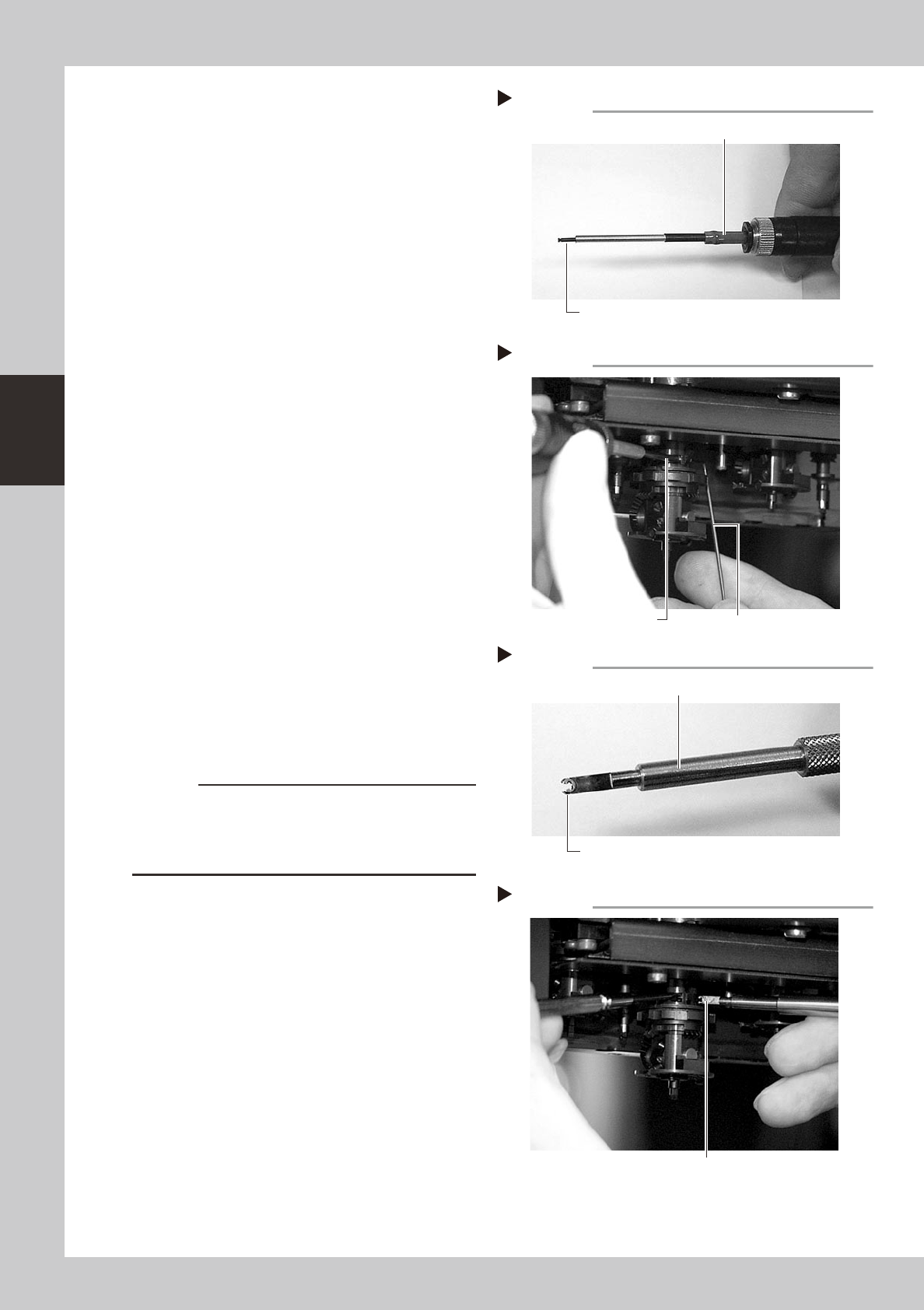
3
Lubricate the FNC lock pin.
Use the lubrication syringe (KV8-M8870-00X)
and turbine oil (VG32) to apply one or two
drops of oil to the FNC lock pin and then
spread it with your finger.
Disassembled parts
Step 1
FNC lock pin
Cam pin
Cam
Spring
FNC lock pin
Cam pin
Cam
Spring
Cleaning the lock pin insertion section
Step 2
Cotton swab stick moistened with alcohol
3-33
3
Periodic maintenance items
4
Reattach the FNC lock pin and
nozzle assembly.
1. Insert the FNC lock pin and spring into
the spline shaft.
2. With the Type 202F nozzle pointing
downwards, insert the FNC nozzle
assembly into the spline shaft until it
pushes the FNC lock pin up slightly.
3. Insert the bevel gear and shaft into the
center hole of the FNC nozzle assembly,
and then insert the stopper block from
the side so that the FNC nozzle assembly
won’t drop down.
53354-F8-00
53355-F8-00
5
Reattach the cams.
Pinch the cam with tweezers and insert it
into the slit of the index holder. Then insert
the custom wire (KV8-M88E2-00X) into the
hole where the cam pin is inserted, to
temporarily position the cam.
53356-F8-00
Inserting the FNC lock pin
Step 4-2
FNC nozzle assembly
FNC lock pin
Inserting the stopper block
Step 4-3
Stopper block
Attaching the cam
Step 5
Insert the cam.
3-34
3
Periodic maintenance items
6
Insert the cam pin.
1. Connect the air tube of the vacuum
pencil (KV8-M8888-A0X) to an air
connector on the machine, and pick up
the cam pin (E-ring end) with the nozzle
of the vacuum pencil.
2. While pressing the custom wire
temporarily inserted in step 5, insert the
cam pin picked up at the nozzle tip of
the vacuum pencil, into the original
position of the index holder.
3. After inserting the cam pin into position,
disconnect the air tube of the vacuum
pencil from the air connector on the
machine.
53357-F8-00
53358-F8-00
7
Reattach the other cam to the
opposite side of the index holder.
Use the same procedure in steps 5 and 6.
8
Fit the E-ring to the cam pin.
1. Set a new E-ring onto the tip of the E-ring
inserter (KV8-M88E1-00X).
Align the E-ring opening with the E-ring
inserter. (Don't worry about front or back
side of the E-ring.)
2. While pressing the cam pin with your
finger from the end with the E-ring, fit the
new E-ring into the groove on the cam
pin.
53359-F8-00
53360-F8-00
c
CAUTION
Check that the E-ring fits securely into position, by
probing it with tweezers, etc.
If the E-ring does not fit properly, it may have stretched
or deformed so use a new E-ring.
Cam pin picked up by vacuum pencil
Step 6-1
Vacuum pencil
Cam pin picked up on the vacuum pencil tip
Inserting the cam pin
Step 6-2
Insert the cam pin.
Custom wire
E-ring set on E-ring inserter
Step 8-1
Set an E-ring on tip.
E-ring inserter
Inserting the E-ring
Step 8-2
Fit the E-ring into the groove on the cam pin.