YG200_YG200L_Mainte_E.pdf - 第75页
3-35 3 Periodic maintenance items 9 I n s t a l l t h e F N C n o z z l e a s s e m b l i e s . R e a s s e m b l e t h e F N C n o z z l e a s s e m b l i e s b y r e f e r r i n g t o s e c t i o n 1 . 2 . 3 , " R…
3-34
3
Periodic maintenance items
6
Insert the cam pin.
1. Connect the air tube of the vacuum
pencil (KV8-M8888-A0X) to an air
connector on the machine, and pick up
the cam pin (E-ring end) with the nozzle
of the vacuum pencil.
2. While pressing the custom wire
temporarily inserted in step 5, insert the
cam pin picked up at the nozzle tip of
the vacuum pencil, into the original
position of the index holder.
3. After inserting the cam pin into position,
disconnect the air tube of the vacuum
pencil from the air connector on the
machine.
53357-F8-00
53358-F8-00
7
Reattach the other cam to the
opposite side of the index holder.
Use the same procedure in steps 5 and 6.
8
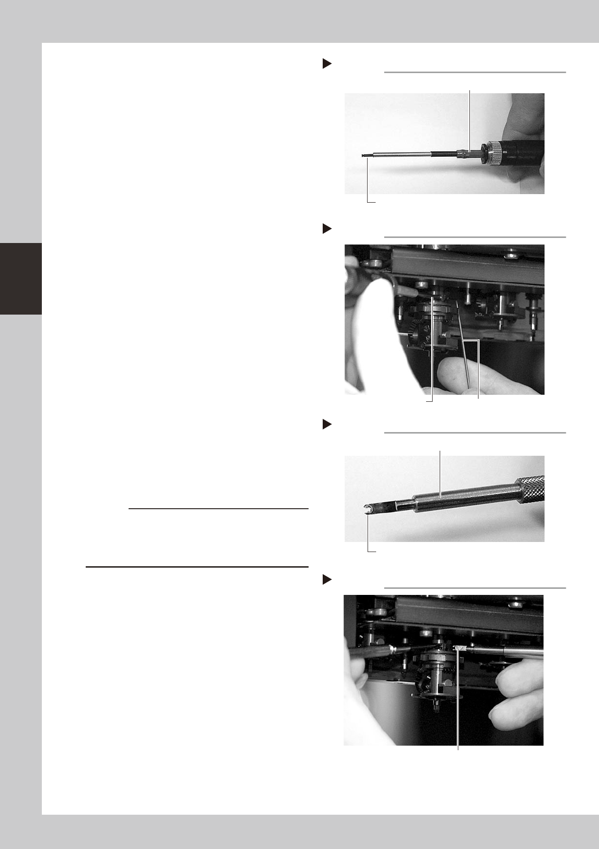
Fit the E-ring to the cam pin.
1. Set a new E-ring onto the tip of the E-ring
inserter (KV8-M88E1-00X).
Align the E-ring opening with the E-ring
inserter. (Don't worry about front or back
side of the E-ring.)
2. While pressing the cam pin with your
finger from the end with the E-ring, fit the
new E-ring into the groove on the cam
pin.
53359-F8-00
53360-F8-00
c
CAUTION
Check that the E-ring fits securely into position, by
probing it with tweezers, etc.
If the E-ring does not fit properly, it may have stretched
or deformed so use a new E-ring.
Cam pin picked up by vacuum pencil
Step 6-1
Vacuum pencil
Cam pin picked up on the vacuum pencil tip
Inserting the cam pin
Step 6-2
Insert the cam pin.
Custom wire
E-ring set on E-ring inserter
Step 8-1
Set an E-ring on tip.
E-ring inserter
Inserting the E-ring
Step 8-2
Fit the E-ring into the groove on the cam pin.
3-35
3
Periodic maintenance items
9
Install the FNC nozzle assemblies.
Reassemble the FNC nozzle assemblies by
referring to section 1.2.3, "Reassembling the
FNC nozzle assembly" in this chapter.
0
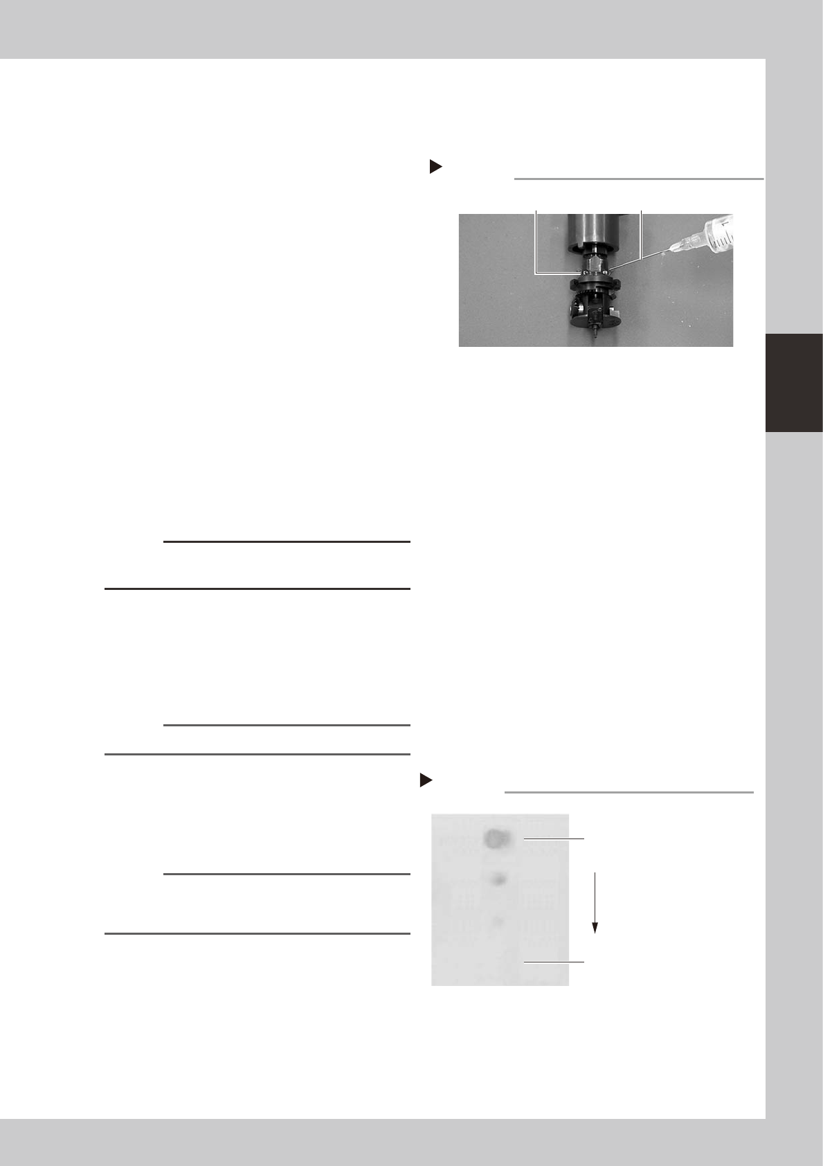
Lubricate each part.
Lubricating oil has been cleaned away by
IPA cleaning, so lubricate the following
parts. Prepare the oil syringe applicator
(KV8-M8870-00X) filled with turbine oil
(VG32).
1. On standard heads, apply one drop of
oil into the elongated holes at the joint
between the nozzle holder and the spline
shaft. (2 holes on each head) After
applying the oil, move the nozzle holder
up and down several times.
2. On FNC heads, pull down the FNC index
holder, and you will see two small cams
on the FNC spline shaft. Apply one drop
of oil onto each cam and then move the
cams up and down several times.
3. Apply one drop of oil to the inner side of
the FNC bevel gear and shaft, and then
spread out the oil with your finger.
53345-F8-00
c
CAUTION
Do not lubricate the bevel gear section, as oil attracts
dust or debris which might get caught in the gear.
q
Remove excess oil.
Using the air blow gun, blow air for about 5
seconds from the nozzle tip, and for about 5
seconds from the nozzle attachment side.
Repeat this process a few times to remove
excess turbine oil remaining in the nozzle.
n
NOTE
A thin coat of oil is enough to lubricate the slide section.
w
Check that the oil was removed.
If needed, blow air through the nozzle again
while using commercially-available oil
blotting paper, and check for residual oil in
the nozzle.
n
NOTE
Performing step 11 is usually sufficient to remove oil
remaining in the nozzle. However, if oil still remains then
blow air through the nozzle once again.
53371-F8-00
Lubrication point
Step 10
FNC cam parts Lubrication syringe
Step 12
Checking for residual oil
Oil blotting paper
Oil will appear after blowing air (first
time) for about 5 seconds from the
nozzle tip.
Repeat the air blow for about 5
seconds each from the nozzle tip
and from the attachment side.
This task is finished when oil no
longer appears.
3-36
3
Periodic maintenance items
e
Reattach the nozzles.
Attach the nozzles back to the head after
checking one more time that there is no oil
remaining there.
r
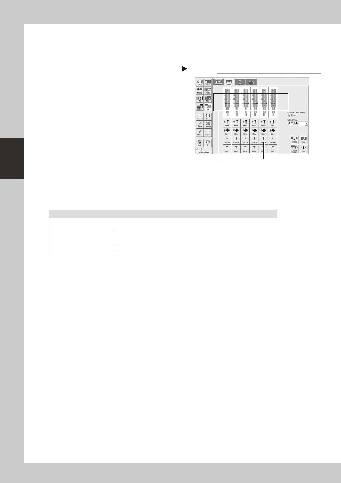
After assembly, check the vacuum
levels.
1. Change the nozzle of each FNC head to
Type 203F, while leave nozzles detached
from the standard heads.
2. Open the [Unit]-[Head] tab screen and
press the [Vacuum] button to generate a
negative pressure. Read the "Max" values
shown in red on the screen and
determine whether the vacuum levels
are appropriate by referring to the table
below.
54302-
F
8-00
t
Perform nozzle change.
On the [Unit]-[Head] tab screen, press the
[Nozzle Change] button to perform nozzle
change and make sure that the nozzles are
changed correctly.
n
Vacuum level in spline shaft air path
Nozzle
Typical criteria
FNC head with Type 203F
nozzle
If the "Max" value is less than 100 while the nozzle is open, the vacuum level is
normal.
If the "Max" value is more than 170 while the nozzle is sealed, the vacuum level
is normal.
Standard head with no nozzle
If the "Max" value is less than 80 while open, the vacuum level is normal.
If the "Max" value is more than 180 while sealed, the vacuum level is normal.
* The vacuum level in the spline shaft air path might sometimes differ slightly depending on the air source and
operating conditions. Use the above criteria values for reference during maintenance.
Step 14
Checking the negative pressures
[Vacuum] button
Read "Max. values".