YG200_YG200L_Mainte_E.pdf - 第79页
4-2 4 How to replace consumable parts 2 . A i r j o i n t 1 Pr e s s t h e e m e r g e n c y s t o p b u t t o n . e T h e m a c h i n e m u s t b e i n e m e r g e n c y s t o p t o e n s u r e s a f e t y d u r i n g w…
4-1
4
How to replace consumable parts
1. Nozzle leaf springs
1
Press the emergency stop button.
e
The machine must be in emergency stop to
ensure safety during work.
2
Remove the nozzle.
Remove the nozzle attached to the leaf
springs to be replaced, by pulling it
downwards by hand.
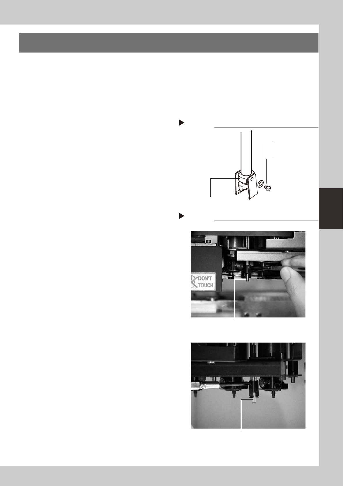
3
Remove the leaf springs.
Use a Phillips precision screwdriver to loosen
the screws securing the defective leaf
springs and remove the leaf springs from the
nozzle holder while pressing the nozzle shaft
from the back.
53400-F8-00
4
Attach new leaf springs.
While pressing the nozzle shaft from the
back, tighten the screw with the Phillips
precision screwdriver to assemble the leaf
spring. At this point, do not forget to fit the
washer.
53401-F4-00
5
Check the assembled condition.
1. Check the gap between the leaf springs
and nozzle.
2. Attempt detaching and attaching a
nozzle several times to check that there
is no looseness.
Removing leaf springs
Step 3
Nozzle leaf spring
mounting washer
Nozzle holder
Nozzle leaf spring
mounting screw
Step 4
YG200
YG200L
Attaching leaf springs
Attach the leaf spring while pressing the opposite
side of the screw.
Attach the leaf spring while pressing the opposite
side of the screw.
4-2
4
How to replace consumable parts
2. Air joint
1
Press the emergency stop button.
e
The machine must be in emergency stop to
ensure safety during work.
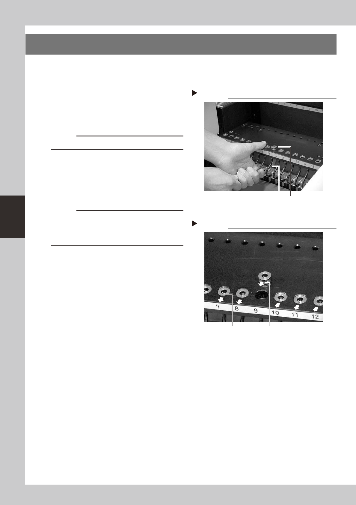
2
Remove the defective air joint.
Insert an M8 hex wrench at the bottom of
the air joint and push it up, then take the air
joint out.
53402-F8-00
c
CAUTION
Be careful not to damage the air hoses.
3
Install a new air joint.
While holding the air joint so the mark (notch)
faces the front side of the machine, insert it
into position from the top of the feeder
plate.
53403-F8-00
c
CAUTION
Make sure that the mark (notch) faces the front side of
the machine. If the air joint is inserted without aligning
the mark orientation, dust or debris may penetrate into
the air hose.
4
Check the operation.
1. Install a feeder at the new air joint
position.
2. Open the [Unit]-[Feeder] tab screen and
check the feeder on/off operation.
Removing the air joint
Step 2
Air joint
Hex wrench
Installing an air joint
Step 3
Mark orientation
Concave mark
4-3
4
How to replace consumable parts
3. Ejector valves
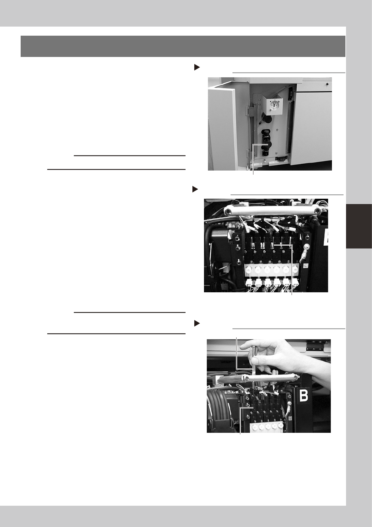
1
Shut off the air supply and turn off
the machine.
Turn the sir supply/shutoff switch to the right
to cut off the air supply, quit the software,
and turn off the machine power switch.
53404-F8-00
2
Cut off the cable ties.
Use nippers to cut off the cable ties binding
the entire harness wires on the top of the
head assembly.
c
CAUTION
Be careful not to cut the harness wires.
3
Unplug the connectors.
Unplug the connectors of the blow valve
and vacuum ejector valve to be replaced.
(The ejector valve connectors are located
behind the blow valves.)
53405-F8-00
4
Remove the blow valve.
Move the harness wires inwards on the head
assembly. There is the bracket frame with
openings, and you can see the blow valve
mounting screws through these openings.
Use the Phillips precision screwdriver to
loosen the two screws securing the blow
valve to the vacuum ejector valve to be
replaced, then remove the blow valve.
53406-F8-00
c
CAUTION
Be careful not to drop the gasket fitted to the backside
of the blow valve.
Shutting off the air supply
Step 1
Air supply/shutoff switch
Removing the blow valve
Step 4
Blow valve
Phillips precision screwdriver
Unplugging the connectors (YG200)
Step 3
Unplug the blow valve connectors (front)
and ejector valve connectors (rear).