YG200_YG200L_Mainte_E.pdf - 第71页
3-31 3 Periodic maintenance items 9 R e m ov e t h e F N C n o z z l e a s s e m b l y . W h i l e g r i p p i n g t h e n o z z l e a s s e m b l y , p u l l o u t t h e F N C n o z z l e s h a f t h o r i z o n t a l l…
3-30
3
Periodic maintenance items
5
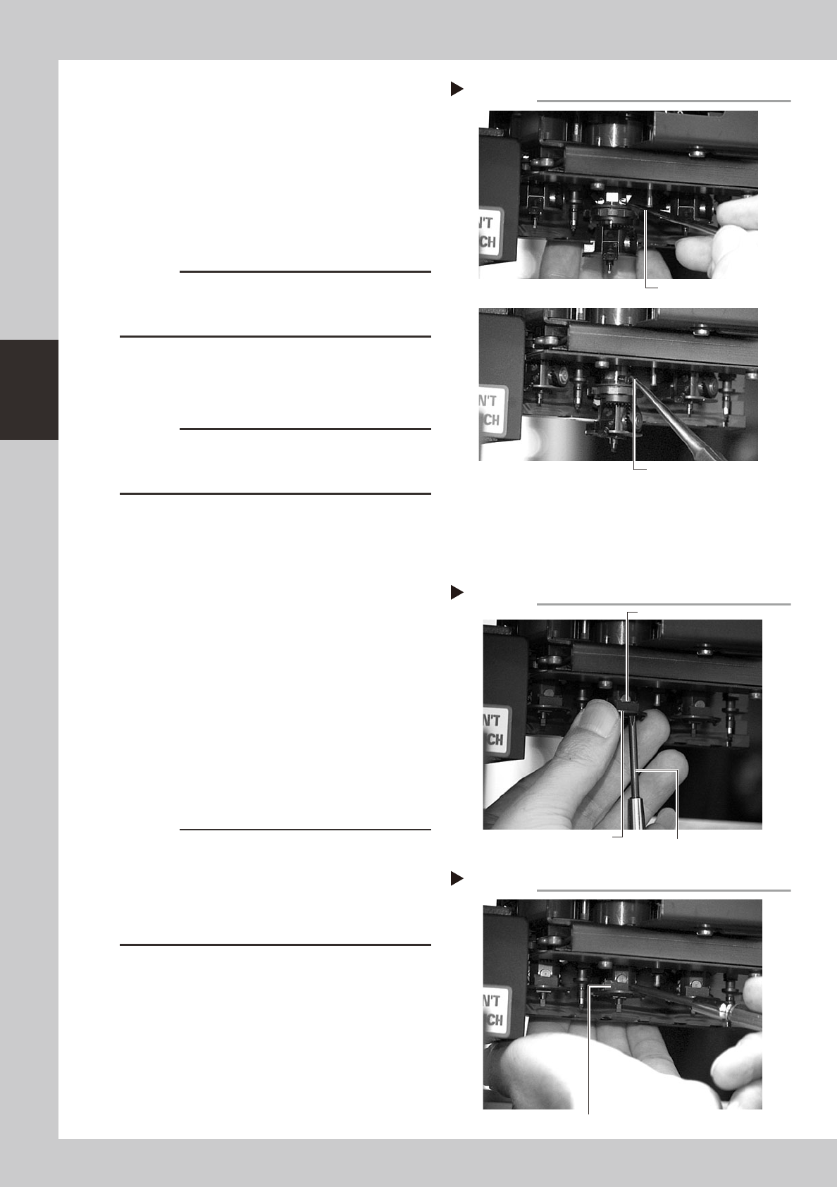
Remove the cam pin and cam.
1. Use tweezers or similar pointed tool to
push the cam pin from the end where
the E-ring was removed.
2. Pinch the opposite end of the pin cam
and pull it out from the index holder.
3. When the cam still stays in the index
holder, remove it with finger or tweezers.
53347-F8-00
c
CAUTION
When pulling out the cam pin in substep 2, the cam
may drop down, so place your palm under the spline
shaft.
6
Remove the other cam.
Use the same procedure in steps 5 and 6 to
remove E-ring, cam pin and cam.
c
CAUTION
The cams and cam pins are very small. Be careful not
to lose them during work. We recommend you prepare
spare parts.
7
Remove the black seal (KV8-
M71RH-00X) on the bottom of the
FNC head.
A black seal is affixed to the bottom of each
FNC head (Heads 2, 4 and 6) to cover the
screws that secure the stopper block.
Remove this black seal to loosen the screws
in the next step.
8
Remove the stopper block.
1. Use the Phillips screwdriver to remove the
two screws securing the stopper block to
the FNC head from the bottom.
2. Remove the stopper block by sliding it
out.
53348-F8-00
53349-F8-00
c
CAUTION
• When loosening the stopper block screws, hold the
edge of the FNC assembly so it won't rotate.
The spline belt might otherwise slip on the gear teeth.
• The screwdriver bit size might slightly differ between
manufacturers. Use the screwdriver that matches the
recessed pattern on the screw head.
Removing the cam pin.
Step 5
Push in the cam.
Pull out the cam.
Removing the stopper block
Step 8-1
Phillips screwdriver
Loose the screw
while holding this edge.
Stopper block
Removing the stopper block
Step 8-2
Slide out the stopper block by pushing it with a fingertip.
3-31
3
Periodic maintenance items
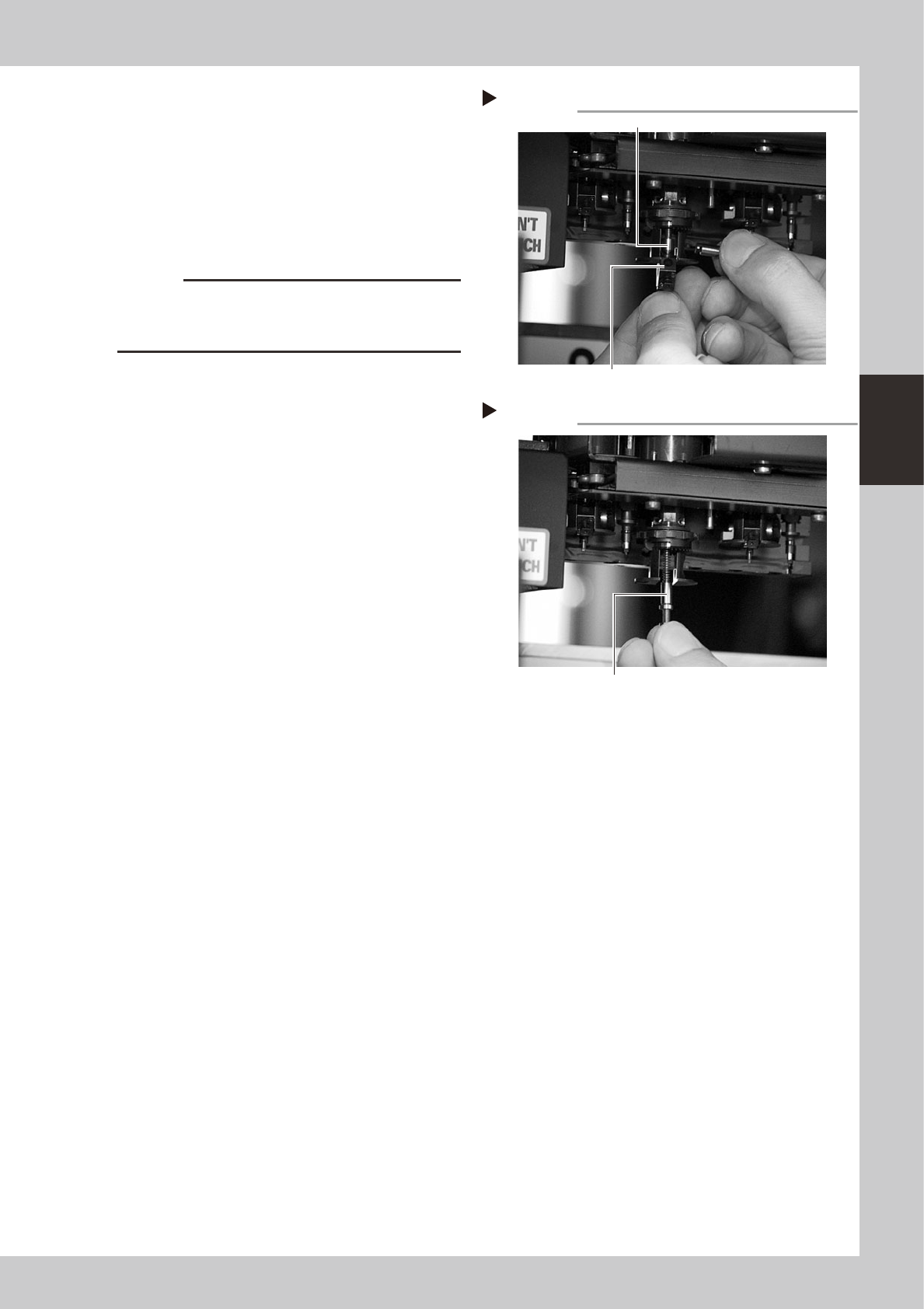
9
Remove the FNC nozzle assembly.
While gripping the nozzle assembly, pull out
the FNC nozzle shaft horizontally along with
the bevel gear and remove the nozzle
assembly by pulling it down.
The FNC lock pin and spring inside the spline
shaft may slide down at this point, so be
careful not to lose them.
53350-F8-00
c
CAUTION
Do not mix up the nozzle assemblies, bevel gears and
shafts of the different heads. Keep them as the original
set for each FNC head.
0
Take out the FNC lock pin and
spring.
When the FNC lock pin and spring still remain
in the spline shaft, pull them out down.
53351-F8-00
Removing the FNC nozzle assembly
Step 9
FNC lock pin
FNC nozzle assembly
Removing the lock pin and spring
Step 10
Take out the FNC lock pin and spring.
3-32
3
Periodic maintenance items
3.3.2 Cleaning and reassembling the FNC lock pin
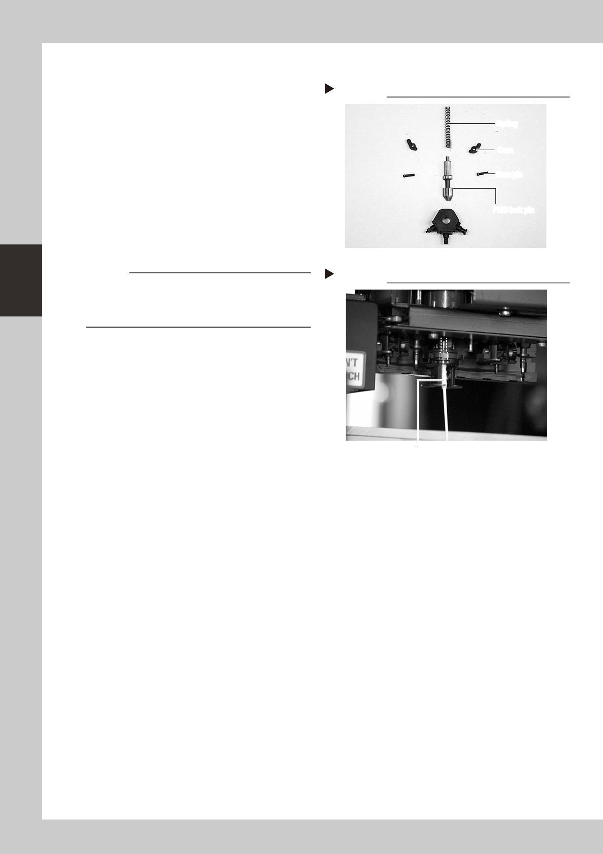
1
Clean the FNC lock pin parts.
Use a cloth moistened with alcohol to wipe
the FNC lock pin, spring, cams and cam
pins.
53352-F8-00
2
Clean the FNC lock pin insertion
section.
1. Blow air into the air path of the FNC lock
pin insertion section of the spline shaft.
2. Use a lint-free cotton swab, moistened
with alcohol, to wipe the FNC lock pin
insertion section.
53353-F8-00
Reference
Before reassembling the FNC lock pin parts, clean the
spline shaft.
Use spiral-tip cotton swabs (thickness: 4mm or less) that
are commercially available.
3
Lubricate the FNC lock pin.
Use the lubrication syringe (KV8-M8870-00X)
and turbine oil (VG32) to apply one or two
drops of oil to the FNC lock pin and then
spread it with your finger.
Disassembled parts
Step 1
FNC lock pin
Cam pin
Cam
Spring
FNC lock pin
Cam pin
Cam
Spring
Cleaning the lock pin insertion section
Step 2
Cotton swab stick moistened with alcohol