YG200_YG200L_Mainte_E.pdf - 第81页
4-4 4 How to replace consumable parts 5 R e m ov e t h e e j e c t o r v a l v e . W h e n t h e b l o w v a l v e i s r e m o v e d , y o u w i l l s e e t h e t w o s c r e w s s e c u r i n g t h e e j e c t o r v a l…
4-3
4
How to replace consumable parts
3. Ejector valves
1
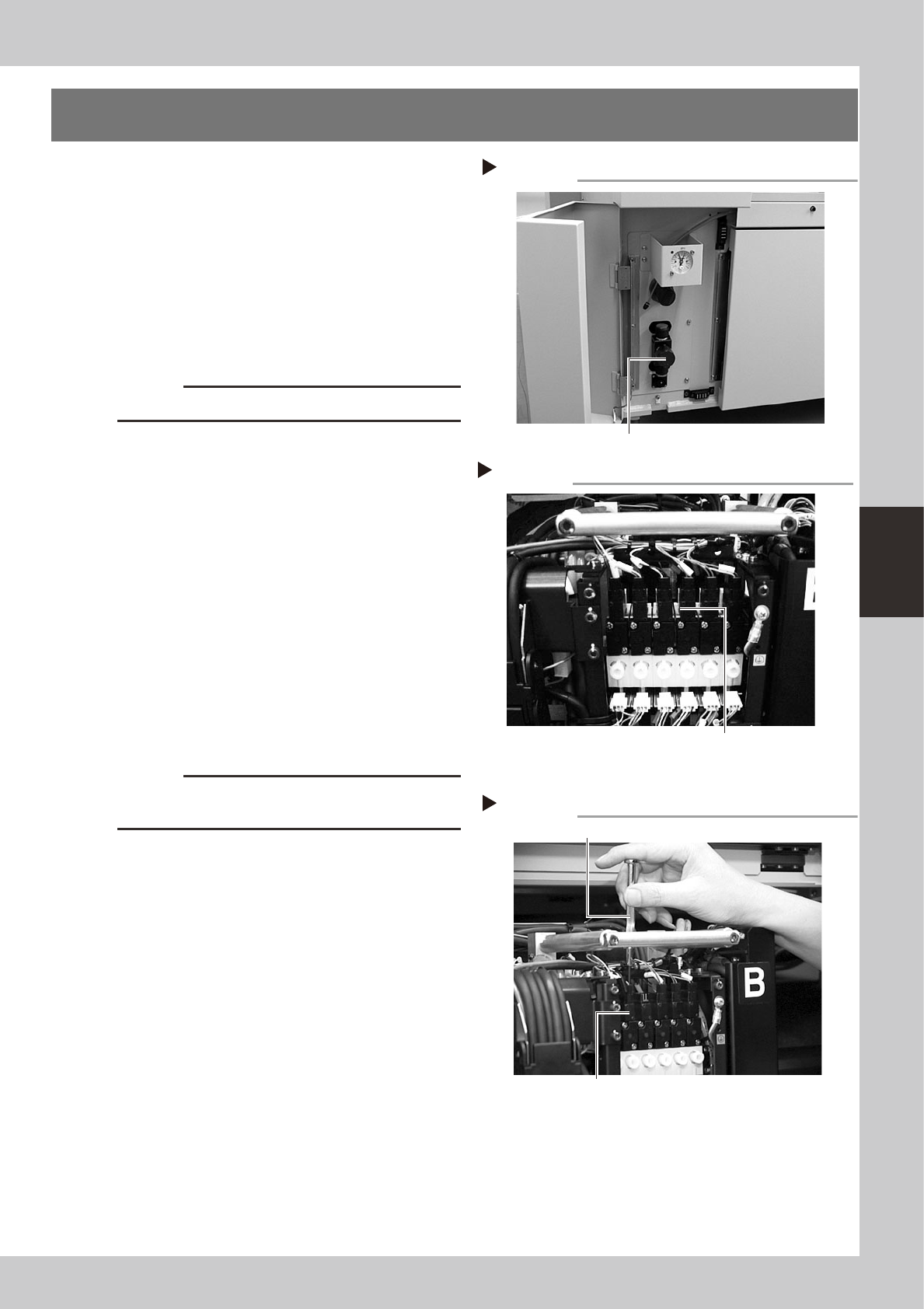
Shut off the air supply and turn off
the machine.
Turn the sir supply/shutoff switch to the right
to cut off the air supply, quit the software,
and turn off the machine power switch.
53404-F8-00
2
Cut off the cable ties.
Use nippers to cut off the cable ties binding
the entire harness wires on the top of the
head assembly.
c
CAUTION
Be careful not to cut the harness wires.
3
Unplug the connectors.
Unplug the connectors of the blow valve
and vacuum ejector valve to be replaced.
(The ejector valve connectors are located
behind the blow valves.)
53405-F8-00
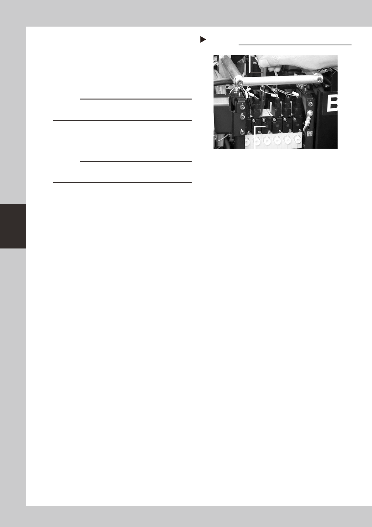
4
Remove the blow valve.
Move the harness wires inwards on the head
assembly. There is the bracket frame with
openings, and you can see the blow valve
mounting screws through these openings.
Use the Phillips precision screwdriver to
loosen the two screws securing the blow
valve to the vacuum ejector valve to be
replaced, then remove the blow valve.
53406-F8-00
c
CAUTION
Be careful not to drop the gasket fitted to the backside
of the blow valve.
Shutting off the air supply
Step 1
Air supply/shutoff switch
Removing the blow valve
Step 4
Blow valve
Phillips precision screwdriver
Unplugging the connectors (YG200)
Step 3
Unplug the blow valve connectors (front)
and ejector valve connectors (rear).
4-4
4
How to replace consumable parts
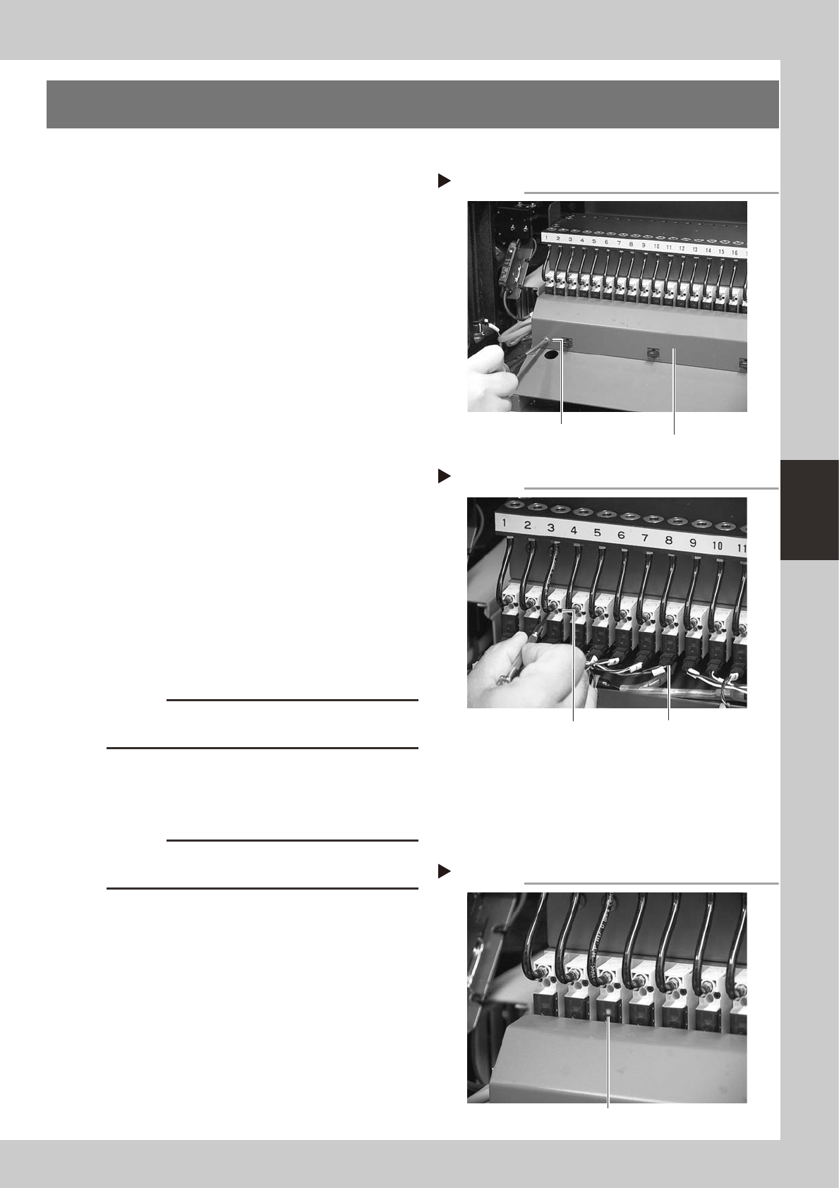
5
Remove the ejector valve.
When the blow valve is removed, you will
see the two screws securing the ejector
valve. Use the Phillips precision screwdriver
to loosen the two screws and remove the
ejector valve.
53407-F8-00
c
CAUTION
Be careful not to drop the gasket fitted to the backside
of the ejector valve.
6
Attach a new ejector valve.
Assemble the new ejector valve in the
reverse order of steps 4 and 5.
c
CAUTION
Do not forget to fit the gasket in place. Use caution not
to fit the gasket inside-out or to pinch it.
7
Reconnect the connectors.
Reconnect the connectors of the blow valve
and ejector valve just replaced.
8
Check operation status.
Supply air to the machine and turn on the
power switch. Open the [Unit]-[Head] tab
screen, press the [Vacuum] button and
check that the vacuum level does not
indicate abnormal values.
Removing the ejector valve.
Step 5
Ejector valve
Phillips precision screwdriver
4-5
4
How to replace consumable parts
4. Feeder valves
1
Turn off the machine power switch.
Quit the application software (VGOS) and
turn off the machine power switch by turning
it to the left.
2
Shut off the air supply.
Open the lower left cover on the front of the
machine and tune the air supply/shutoff
switch to the left to cut off the air supply.
3
Remove the wire harness cover.
Use a Phillips screwdriver to loosen and
remove the screws that secure the wire
harness cover to the machine body.
53408-F8-00
4
Remove the feeder valve.
1. Detach the connector from the feeder
valve to be replaced.
2. Use a precision screwdriver to loosen the
two screws and remove the feeder valve.
53409-F8-00
5
Remove the air hose.
Use a cutter to cut off the air hose and
remove it.
6
Attach a new feeder valve and the
wire harness cover.
Assemble the new feeder valve and wire
harness cover in the reverse order of steps 3
and 4.
c
CAUTION
Do not forget to fit the gasket in place. Use caution not
to fit the gasket inside-out or to pinch it.
7
Supply air to the machine.
Turn the air supply/shutoff switch back to the
right to supply air.
c
CAUTION
Always use the air hose supplied along with the air
valves.
8
Check the ejector operation.
1. Turn on the machine.
2. Install a feeder at the new feeder valve
position.
3. Open the [Unit]-[Feeder] tab screen and
check the feeder on/off operation.
53410-F8-00
Removing the wire harness cover
Step 3
Wire harness cover
Remove the screws
at both ends.
Removing the feeder valve
Step 4
Valve connector
Loosen these
two screws.
Checking the feeder valve operation
Step 8
LED lamp