00194932-20 User Manual CAN Test Box-Error Frame Diagnostic unit_en.pdf - 第100页
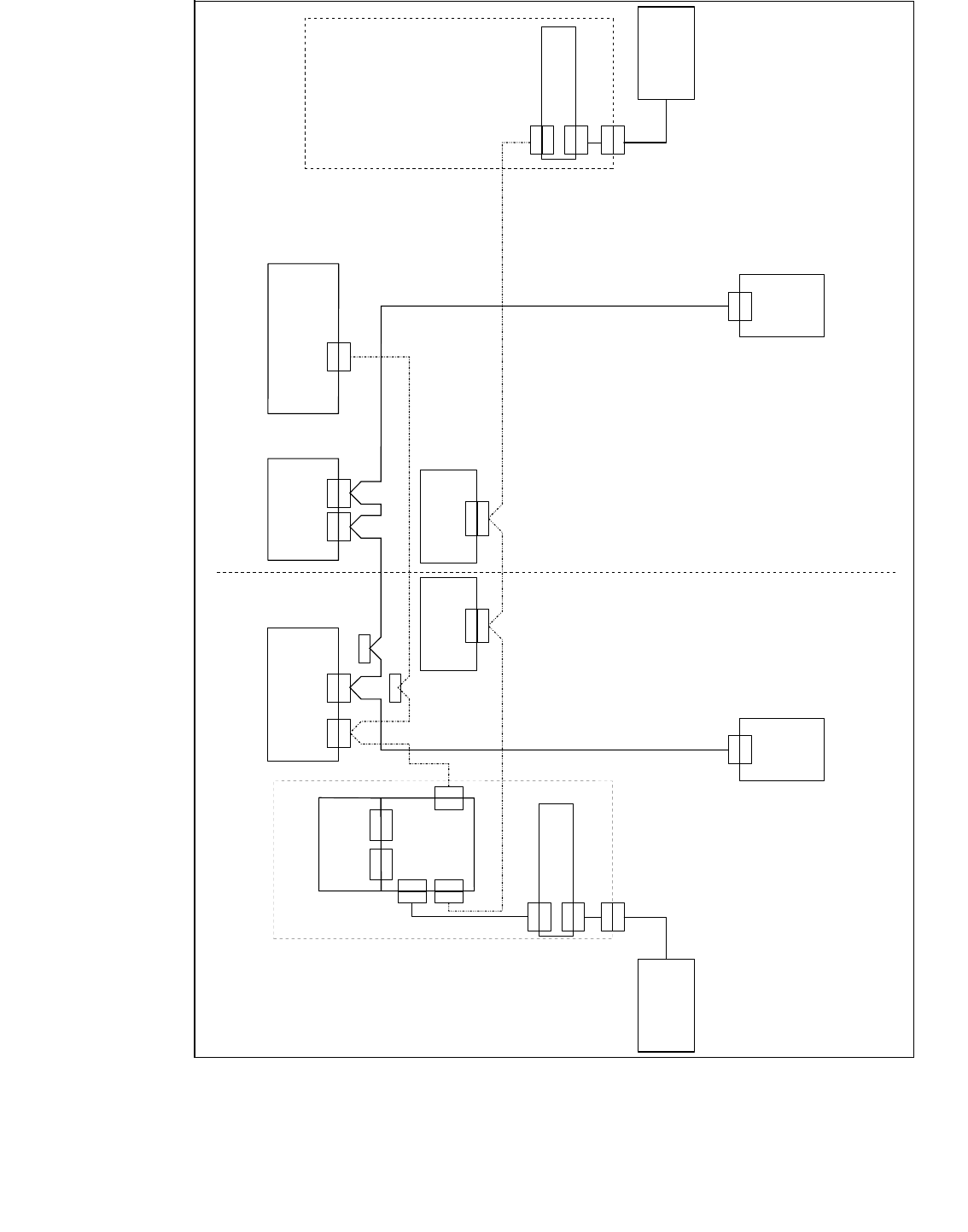
1 - 100 SIPLACE CAN Bus Edition 10/2018 100 4.10.4 CAN Bus with CAN T ermi nator on the D2 in detai l For the D2 machine we use two diff erent CAN Bu s circuits. CAN Bus 1 and CAN Bus 2 are workin g with 1 MBit/s. Fig. 4…
1 - 99
Edition 10/2018 SIPLACE CAN Bus
99
Fig. 4.10 - 6 CAN Bus structure D2 operation diagram 03043798-010302LD3
C A N T e r m i n a t i o n o n :
S 1 . 8 = O N
C A N T e r m i n a t i o n o n :
S 1 . 5 = O N
f i x e d C A N T e r m i n a t i o n o n
G a n t r y H e a d D i s t r i b u t
o r
0 3 0 3 8 0 0 2
f i x e d C A N T e r m i n a t i o n o n
G a n t r y H e a d D i s t r i b u t o r
0 3 0 3 8 0 0 2
C A N I / O m o d u l e
0 0 3 5 5 0 5 1 ( q b )
B E - T i s c h 2
C o m p o n e n t s t a b l e 2
0 3 0 4 1 3 1 5 )
M a s c h i n e n C o n t r o l l e r
M a c h i n e c o n t r o l l e r
0 3 0 3 2 3 4 2 ( p a )
C A N - B U S 1 D 2
A x i s U n i t A 3 6 4
0 3 0 4 2 0 4 7
T r a n s p o r t s t e u e r u n g T S P 2 0 1
C o n v e y o r c o n t r o l l e r T S P 2 0 1
0 3 0 4 3 8 3 2
C A N 2 C A N 1
X 2 2 a o
X 2 2 a o
X 3 0 _ 1 s q
X 3 0 _ 1 s q
X 1 1 p aX 1 2 p a
X 1 1 p a
X 1 b f
H a u p t v e r t e i l e r
M a i n D i s t r i b u t o r
0 3 0 5 0 1 7 8 ( b f )
U n t e r v e r t e i l e r
S u b D i s t r i b u t o r
0 3 0 5 0 1 7 7 ( a f )
S c h l e p p -
V e r t e i l e r
T r a i l i n g
d i s t r i b u t o r
0 3 0 3 8 6 9 0
X 4 0 b a
X 4 0 b a
X 1 b f X 1 a f
X 1 a f
X 3 0 _ 2 s q
X 3 0 _ 2 s q
0 3 0 5 0 1 6 3
X 1 1 p a 2 S e r v i c e
P o r t a l 2 / G a n t r y 2
S e k t o r 2
S e c t o r 2
S e k t o r 1
S e c t o r 1
C A N - B U S 2 S u b
0 3 0 5 0 1 6 5
X 1 q b
X 1 q e
C A N - I n t e r f a c e
0 3 0 3 2 3 4 6 ( q e )
X 4 b h
X 4 b h
X 3 q e
X 3 q e
X 5 q e
X 5 q e
X 4 q e
X 4 q e
G u r t s c h n e i d e r 2
T a p e c u t t e r 2
0 3 0 0 6 4 1 1 ( b h )
G u r t s c h n e i d e r 1
T a p e c u t t e r 1
0 3 0 0 6 4 1 1 ( a h )
X 1 r b
X 1 r b
X 2 r b
X 2 r b
B E - T i s c h 1
C o m p o n e n t s t a b l e 1
0 3 0 4 1 3 1 5
C A N - B U S t e r m i n a t o r
c o m p o n e n t t a b l e
0 3 0 4 6 8 6 3
X 4 a h
X 4 a h
X 1 q a
X 1 q a
X 2 q a
X 2 q a
C A N - B U S t e r m i n a t o r
c o m p o n e n t t a b l e
0 3 0 4 6 8 6 3
X 2 q b
X 2 q e
S c h l e p p -
V e r t e i l e r
T r a i l i n g
d i s t r i b u t o r
0 3 0 3 8 6 9 0
X 4 0 a a
X 4 0 a a
P o r t a l 1 / G a n t r y 1
X 1 2 p a 2 S e r v i c e
X 1 2 p a
C A N - B U S 2 D 2
0 3 0 5 0 6 6 6
1 - 100
SIPLACE CAN Bus Edition 10/2018
100
4.10.4 CAN Bus with CAN Terminator on the D2 in detail
For the D2 machine we use two different CAN Bus circuits. CAN Bus 1 and CAN Bus 2 are working
with 1 MBit/s.
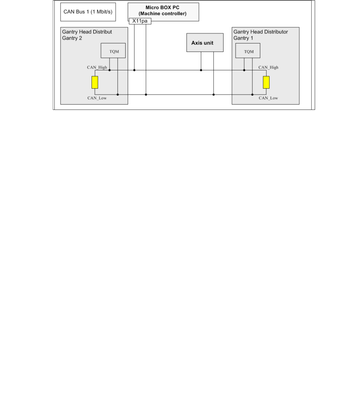
Fig. 4.10 - 7 CAN Bus 1 on the D2 machine
Note to measure the CAN terminator:
In General, the terminator has to measure if the machine is switch off!
In the Fig. 4.10 - 7 for the CAN Bus 1, there are two terminators in the circuit, When the machine
is switch off you have to measure on the serviceconnector X11pa2 a value of 60 Ohm.
1 - 101
Edition 10/2018 SIPLACE CAN Bus
101
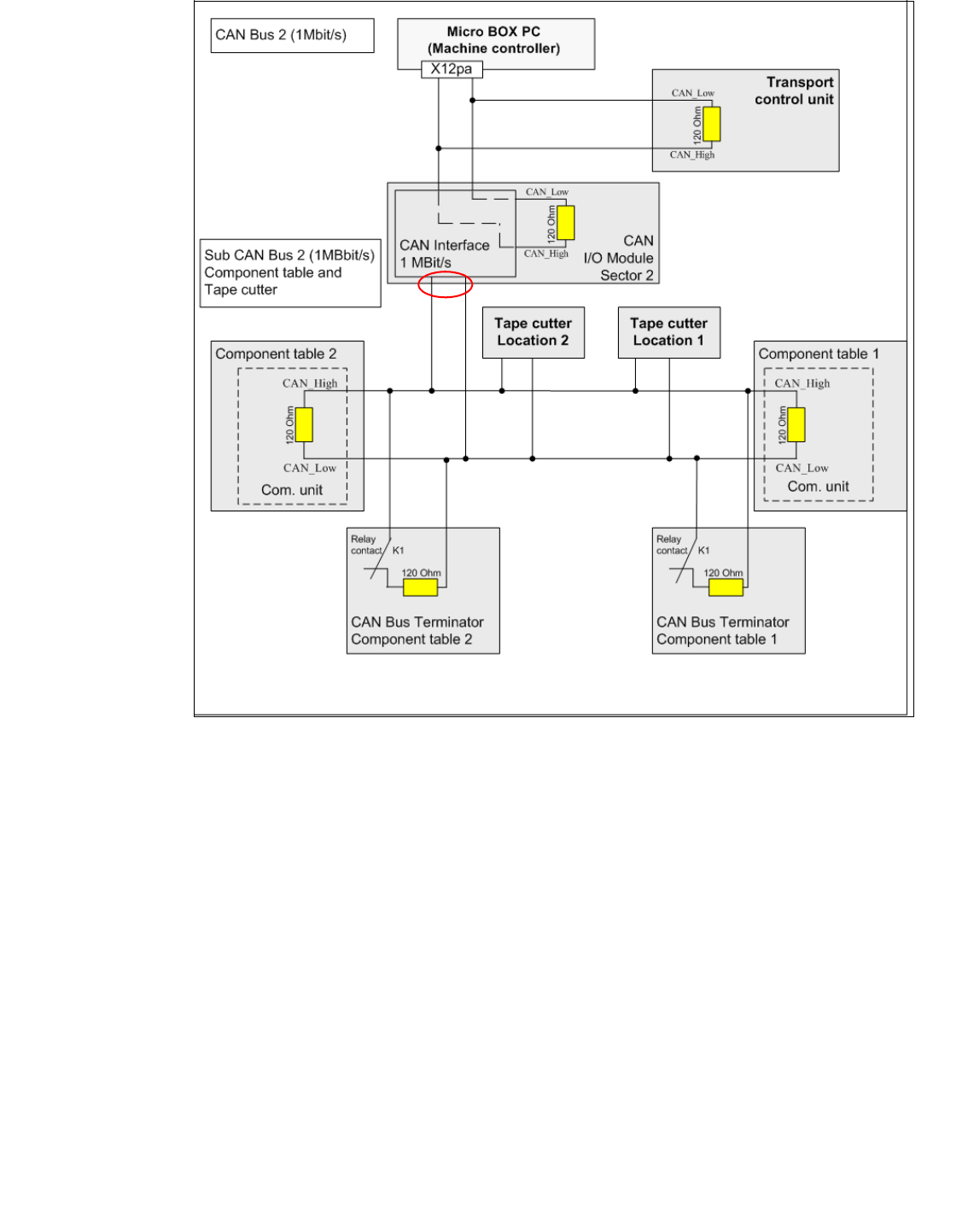
Fig. 4.10 - 8 CAN Bus 2 on the D2 machine
For the CAN Bus 2 (1MBit/s) you have to measure the terminator on the service-connector X12-
pa2. The value should be 60 ohm.
In the Fig. 4.10 - 8 for the component and tape cutter CAN Bus 2, there are four terminators in the
circuit, if the machine switch off and the component table connected. So you measure 30 ohm on
the connector (1).
When the machine is switch on, the Relays contacts K1 will be open and the normal termination
of 60 Ohm is available.
Now, If you change or disconnect a component table, the CAN Bus is working normal, because
the relay contact K1 will be closed and the other terminator is available.
1