00194932-20 User Manual CAN Test Box-Error Frame Diagnostic unit_en.pdf - 第112页
1 - 1 12 SIPLACE CAN Bus Edition 10/2018 11 2 4.12.1 Machine CAN Bus structure SX1 / DX1 (from MA No.N001/May 2015) Fig. 4.12 - 2 Machine CAN Bus structure SX/DX 1
1 - 111
Edition 10/2018 SIPLACE CAN Bus
111
4.12 CAN Bus structure SX / DX - Series (from MA
No.N001/May 2015)
All SX machine with serial number N001, delivered since may 2015 are provided with new hard-
ware:
- Box PC IBASE 402 (03120423-xx)
- CIN Box 4 fold CAN Bus card
- MGCU2 - Modulare Gantry Control Unit (Introduction of the 3-fold MGCU end of 2015)
- Power supply unit - Switched Mode Power Supply (SMPS)
- I/O Module 2
- changed trailling harness
With the introduction of the CAN Interface (03108598-xx CAN Interface CINX) the CAN structure
of the SX machine have not changed. Only the communication between the Station computer and
CIN Box is now via LAN cable, see describtion of the following pages.
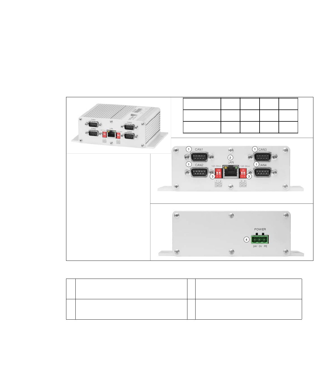
Fig. 4.12 - 1 03108598-xx CAN Interface CINX
1 CAN Bus Connector CAN1-4 (for SX ma-
chine CAN1 and CAN2 is used)
2 LAN Connector CAT 5 cable to PC-
LAN1
3 DIP Switch - setting the terminator of 120
Ohm for CAN1-4
4 Power connector 24V
1234
X-Series SONONONON
SX-Series OFF OFF OFF OFF
1 - 112
SIPLACE CAN Bus Edition 10/2018
112
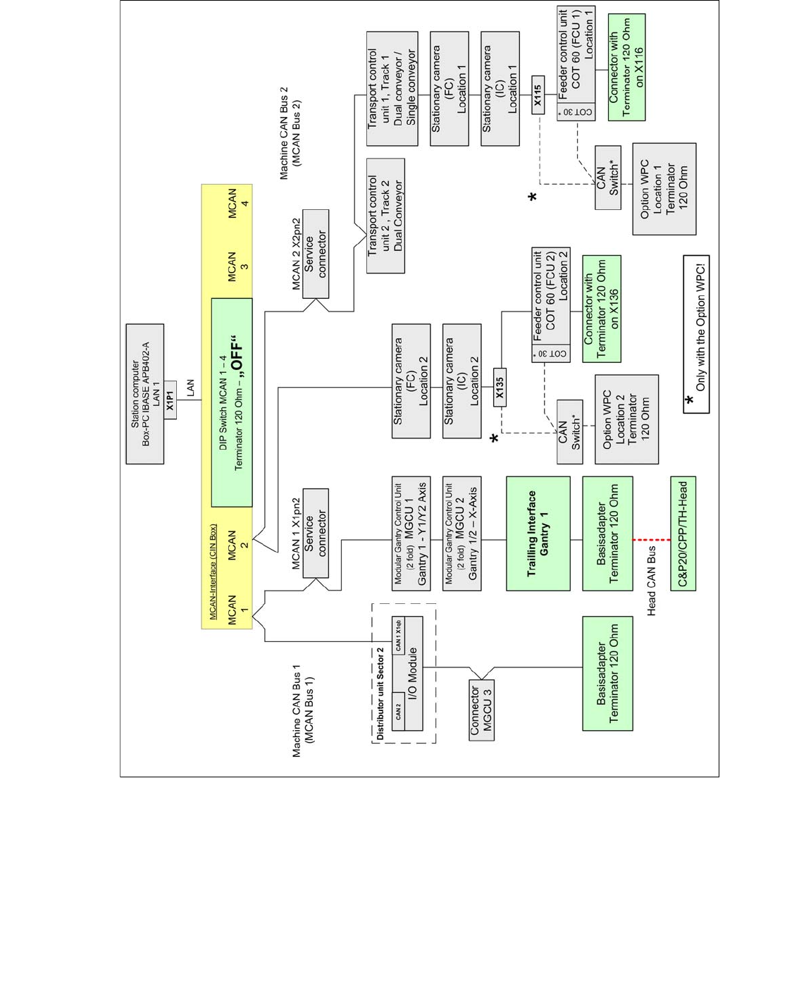
4.12.1 Machine CAN Bus structure SX1 / DX1 (from MA No.N001/May 2015)
Fig. 4.12 - 2 Machine CAN Bus structure SX/DX 1
1 - 113
Edition 10/2018 SIPLACE CAN Bus
113
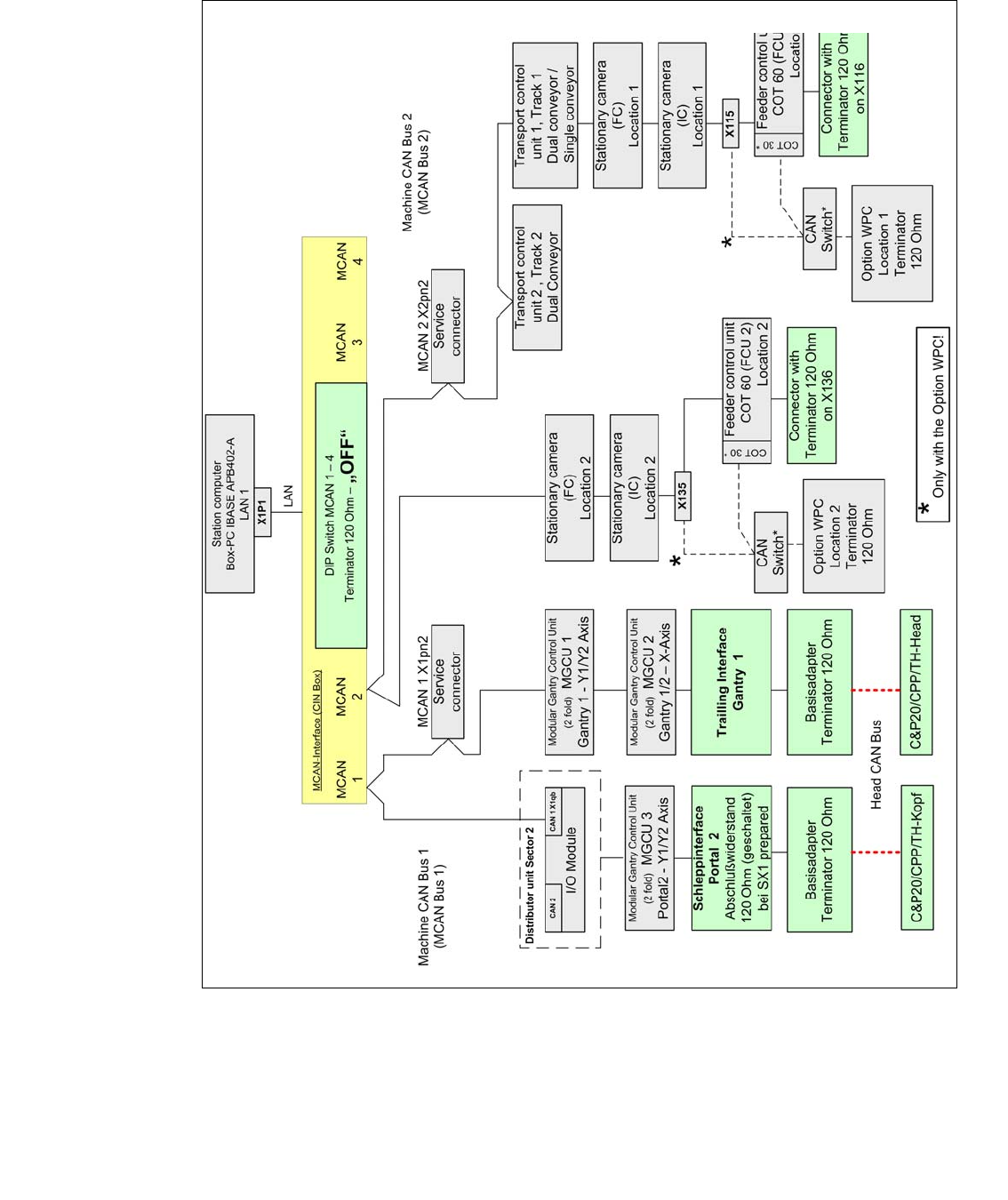
4.12.2 Machine CAN Bus structure SX2 / DX2 (from MA No.N001/May 2015)
Fig. 4.12 - 3 Machine CAN Bus structure SX/DX 2