00194932-20 User Manual CAN Test Box-Error Frame Diagnostic unit_en.pdf - 第153页
1 - 153 Edition 10/2 018 SIPLACE CAN Bus 153 4.18 CAN Bus structure SIPLACE TX-Series (from Nov .2015) The SIPLACE TX machine are configurable as TX2i , with two gantries and table position inner , as TX2 with two g antr…
1 - 152
SIPLACE CAN Bus Edition 10/2018
152
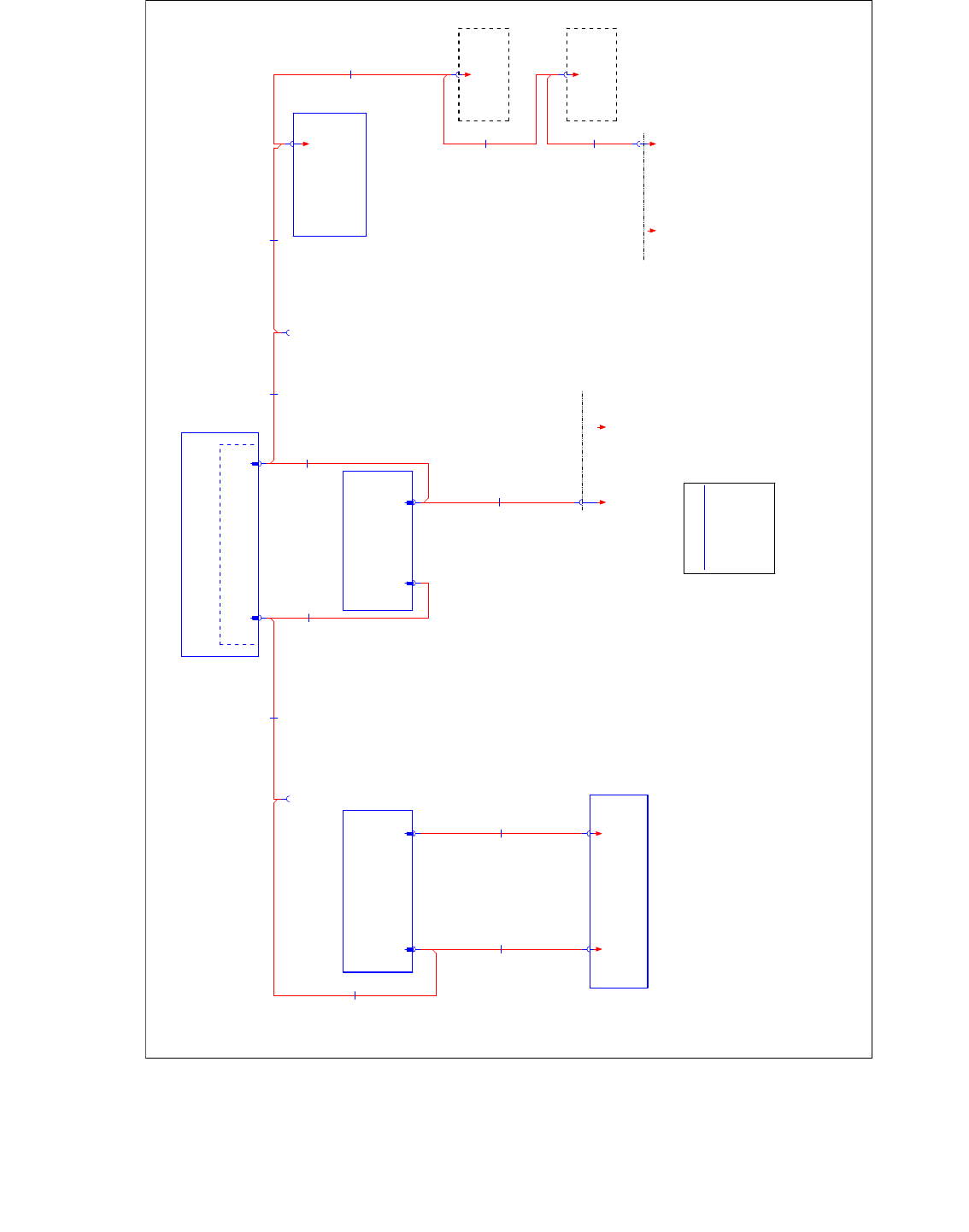
Fig. 4.17 - 4 Machine CAN Bus SIPLACE E-Serie Circuit diagram 90011772-01
&$1%86
&$1%86
&$1%86
&$1%86
&$1EXVZLULQJ
&$1EXVZLULQJ
&$1EXVZLULQJ
&$1EXVZLULQJ
ZLUHQRZLULQJ68%'SLQ
IUHH
*1'
&$1B/
&$1B+
*1'
IUHH
IUHH
IUHH
IUHH
&$1%86
&$1%86
&$1%86
&$1%86
2SWLRQDO
$WWDFKHGIRURQHVLGHGRSHUDWLRQ
2SWLRQDO
2SWLRQDO
2SWLRQDO
2SWLRQDO
)RU&27L/RF
)RU&27L/RF
)RU&27L/RF
)RU&27L/RF
2SWLRQDO
2SWLRQDO
2SWLRQDO
2SWLRQDO
)RU&27L/RF
)RU&27L/RF
)RU&27L/RF
)RU&27L/RF
0*&8
0*&8
0*&8
0*&8
0*&80RWLRQFRQWUROOHU
0*&80RWLRQFRQWUROOHU
0*&80RWLRQFRQWUROOHU
0*&80RWLRQFRQWUROOHU
;2VF
;2VF
;2VF
;2VF
0&$1
;8VF
;8VF
;8VF
;8VF
*&$1
763
763
763
763
DR
DR
DR
DR
SF
SF
SF
SF
&RQWURO&RPSXWHU
&RQWURO&RPSXWHU
&RQWURO&RPSXWHU
&RQWURO&RPSXWHU
;SQ
;SQ
;SQ
;SQ
0&$1
;
;
;
;
&$1
;
;
;
;
&$1
&DEOH&$1%XV0&$1
:
:
:
:
&DEOH&$1%XV0&$1
:
:
:
:
DD
DD
DD
DD
7UDLOLQJ,QWHUIDFH
7UDLOLQJ,QWHUIDFH
7UDLOLQJ,QWHUIDFH
7UDLOLQJ,QWHUIDFH
&DEOH&$1%XV0&$1
:
:
:
:
&DEOH&$1%XV
0&$1
:
:
:
:
;GP
;GP
;GP
;GP
/RFDWLRQ
/RFDWLRQ
/RFDWLRQ
/RFDWLRQ
6WDWLRQDU\)&FDPHUDV
6WDWLRQDU\)&FDPHUDV
6WDWLRQDU\)&FDPHUDV
6WDWLRQDU\)&FDPHUDV
;SQ
;SQ
;SQ
;SQ;SQ
;SQ
;SQ
;SQ
;SQ
;SQ
;SQ
;SQ
6HUYLFH
6HUYLFH
6HUYLFH
6HUYLFH
0&$1
0&$1
0&$1
0&$1
;TE
;TE
;TE
;TE
;SQ
;SQ
;SQ
;SQ
6HUYLFH
6HUYLFH
6HUYLFH
6HUYLFH
0&$1
0&$1
0&$1
0&$1
;2VF
;2VF
;2VF
;2VF
;DD
;DD
;DD
;DD
;8VF
;8VF
;8VF
;8VF
;
;
;
;
SQ
SQ
SQ
SQ
&DQFDUG
&DQFDUG
&DQFDUG
&DQFDUG
&2093&,
TE
TE
TE
TE
$VVHPEO\,2&RQWURO8QLW,,
$VVHPEO\,2&RQWURO8QLW,,
$VVHPEO\,2&RQWURO8QLW,,
$VVHPEO\,2&RQWURO8QLW,,
'LVWULEXWRU
'LVWULEXWRU
'LVWULEXWRU
'LVWULEXWRU
;DP
;DP
;DP
;DP
/RFDWLRQ
/RFDWLRQ
/RFDWLRQ
/RFDWLRQ
6WDWLRQDU\,&FDPHUDV
6WDWLRQDU\,&FDPHUDV
6WDWLRQDU\,&FDPHUDV
6WDWLRQDU\,&FDPHUDV
&DEOH&$1%XV0&$1
:
:
:
:
&DEOH&$1%XV0&$1
:
:
:
:
;DR
;DR
;DR
;DR
&DEOH&$1%XV0&$1
:
:
:
:
&DEOH&$1%XV0&$1
:
:
:
:
&DEOH&$1%XV0&$1
:
:
:
:
;
;
;
;
;DD
;DD
;DD
;DD
&DEOH&$1%XV
*&$1
:
:
:
:
;SQ
;SQ
;SQ
;SQ
0&$1
&DEOH&$1%XV
0&$1
:
:
:
:
;TE
;TE
;TE
;TE
&DEOH&$1%XV0&$1
:
:
:
:
;GP
VW&$0
&$1&2BU
&2
;
&27)&8/RFDWLRQ
&27)&8/RFDWLRQ
&27)&8/RFDWLRQ
&27)&8/RFDWLRQ
0&$1
*$
*&$1
*$
;DP
VW&$0
;
07)&8/RFDWLRQ
07)&8/RFDWLRQ
07)&8/RFDWLRQ
07)&8/RFDWLRQ
$
;
&27)&8/RFDWLRQ
&27)&8/RFDWLRQ
&27)&8/RFDWLRQ
&27)&8/RFDWLRQ
1 - 153
Edition 10/2018 SIPLACE CAN Bus
153
4.18 CAN Bus structure SIPLACE TX-Series (from
Nov.2015)
The SIPLACE TX machine are configurable as TX2i, with two gantries and table position inner, as
TX2 with two gantries and table position 1 outer, or an TX1 with one gantry and the table position
1 outer.
Depends on the machine configuration the result are different CAN Bus structures. In general the
SIPLACE TX operate with three separate CAN Bus networks with a speed of 1MBit/s.
The communication to the subsystems will be carried out via the CIN Box, please consider, that
the terminators on the CIN Box are OFF. The terminators have to be set on the I/O module
(see the following pages).
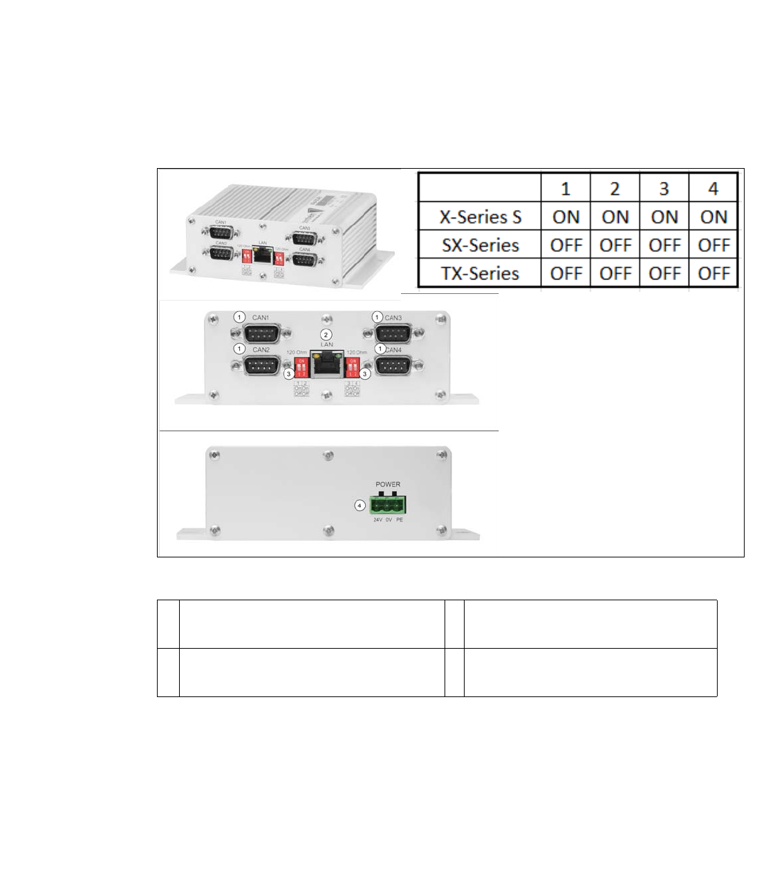
Fig. 4.18 - 1 03108598-xx CAN Interface CINX
1 CAN Bus Connector CAN1-4 2 LAN Connector CAT 5 cable to PC
LAN1
3 DIP Switch - setting the terminator of 120
Ohm for CAN1-4
4 Power connector 24V
1 - 154
SIPLACE CAN Bus Edition 10/2018
154
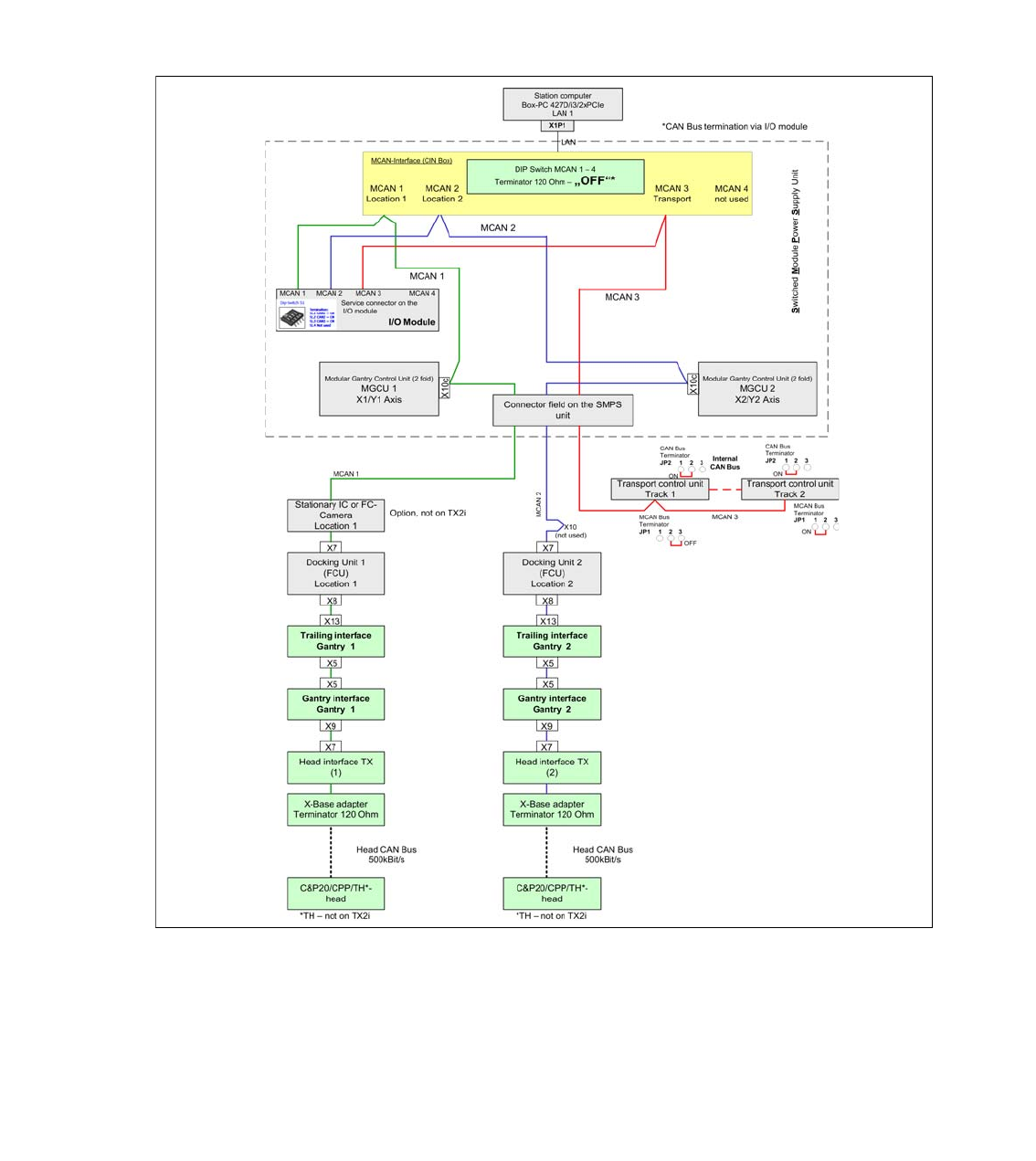
4.18.1 Machine CAN Bus Structure TX2i and TX2
On the SIPLACE TX Machine there are three CAN Bus networks which communicate to the sub-
systems.The service connector for each CAN Bus network are placed directly on the I/O module.
The following overview shows the structure of the CAN Bus. The MCAN 1 communicate with all
subsystems in location 1 (MGCU, FCU, stationary camera, gantry 1). The MCAN 2 communicate
with all subsystems in location 2 (MGCU, FCU, gantry 2) and the MCAN 3 is responsible for the
Transport control unit.
Fig. 4.18 - 2 Machine CAN Bus SIPLACE TX2i and TX2