00194932-20 User Manual CAN Test Box-Error Frame Diagnostic unit_en.pdf - 第32页
1 - 32 SIPLACE CAN Bus Edition 10/2018 32 3.3 Description and settings Fig. 3.3 - 1 Description CAN 1 Fig. 3.3 - 2 Description CAN 2 1. RESET - button, to reset the red LED on both side CAN 1 and CAN 2 of the CAN switch …
1 - 31
Edition 10/2018 SIPLACE CAN Bus
31
Independent of the machine type, each machine has one CAN Bus for each placement area.
This CAN Bus can be disconnect at a adequate point and the CAN switch will be connect in se-
ries. Therefore two independet CAN Bus systems are established. The structur of the CAN Bus
are described in chapter 4 as flow chart and circuit diagram.
If one or more Error frames are received the LED will be red (see red dot in the picture above).
The result is, that the Error Frames comes from the subsystem 1 or 2.
The next step could be to install the CAN Switch between subsysteme 1 and 2. Additionally you
have to check the CAN Bus-cable, whether there is no short cut or other bad connection.To elimi-
nate defect CAN Bus cable you can use CAN test cable.
Note:
The new eSW (GATWAY_0011000A.bhx) on the CAN Switch is necessary to work with the SX
machine and two WPC‘s. With this eSW the initialize procedure of the CAN Switch has a delay
time of 10sec. So therefore you have to wait 10seconds after switch ON the CAN switch before
you start with your Servicework.
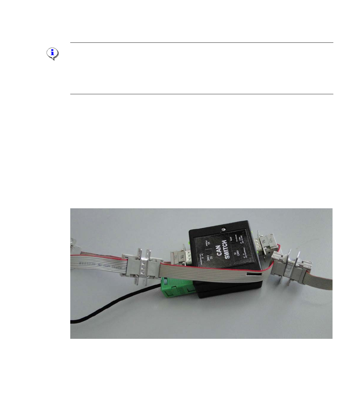
3.2.1 Adapter cable CAN switch
For older machine like the HS50,60, D4, HF and partly for X-series machines the adaptercable is
necessary to transfer the additional signals Power fail, CAN Reset and the 1-wire Bus, which are
integrated in the CAN Bus cable. When we cut the machine CAN Bus into two parts with the CAN
switch box the connection of this signals will be destroyed. Because the CAN switch box transfer
CAN_H and CAN_L signals only.
The adapter cable have to connected for this machine between CAN 1 and CAN 2 of the CAN
switch box. (see picture)
Fig. 3.2 - 2 Adapter cable for the CAN Switch Box
1 - 32
SIPLACE CAN Bus Edition 10/2018
32
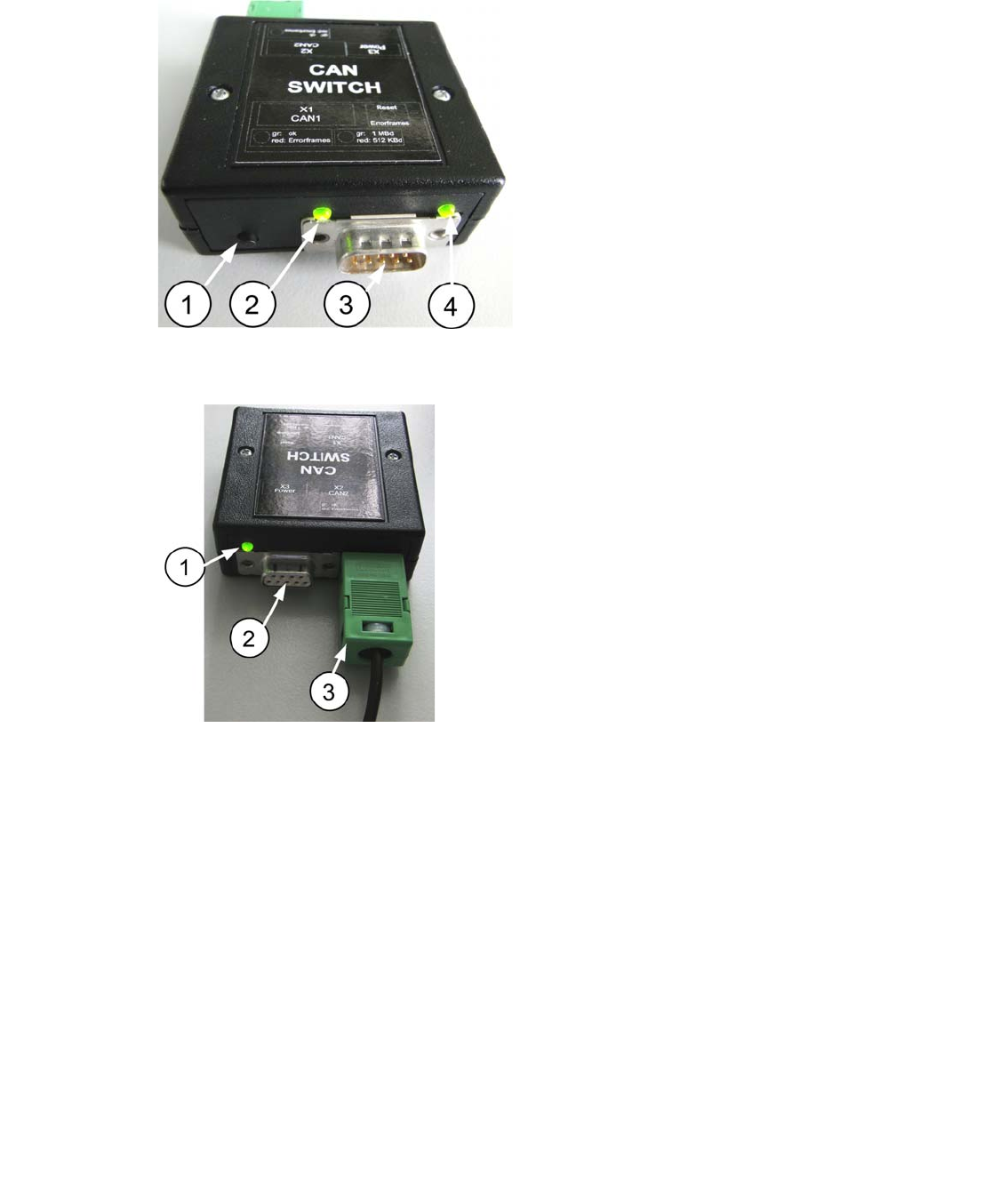
3.3 Description and settings
Fig. 3.3 - 1 Description CAN 1
Fig. 3.3 - 2 Description CAN 2
1. RESET - button, to reset the red LED on
both side CAN 1 and CAN 2 of the CAN
switch
2. LED GREEN Baud rate 500kBit/1MBit
depend on the DIP-Switch setting S1.2
3. Connector CAN Bus cable CAN 1
4. LED Green/Red for CAN 1
Data transfer OK - Green
Error Frames received - Red
1. LED Green/Red for CAN 2
Data transfer OK - Green
Error Frames received - Red
2. Connector CAN Bus cable CAN 2
3. Connector power supply 24V DC
1 - 33
Edition 10/2018 SIPLACE CAN Bus
33
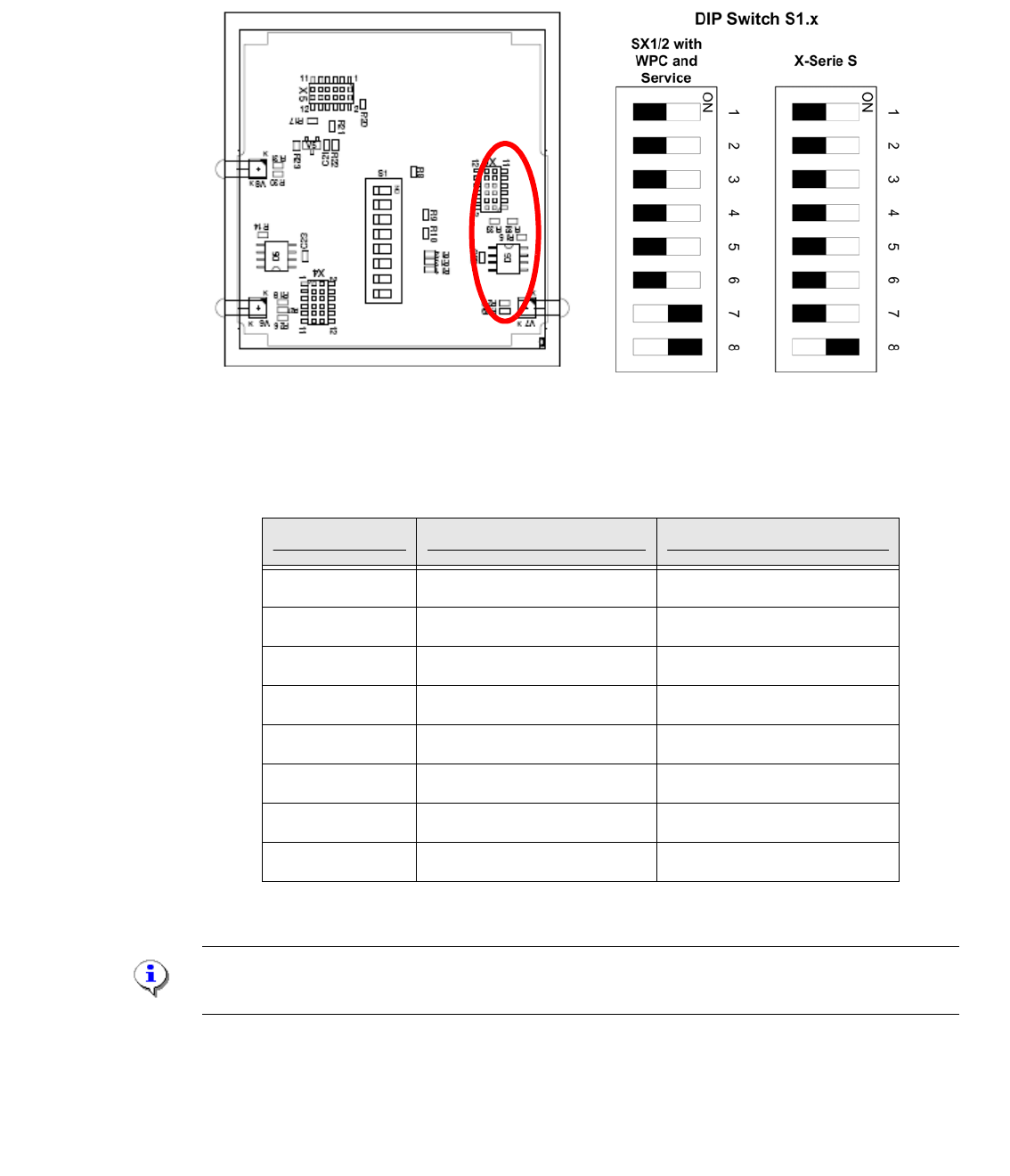
3.3.1 Settings on the DIP switch
To change the DIP switch settings, disconnect the CAN Switch from the power supply and open
the upper part (label) of the CAN switch by loosen the two screws.
Fig. 3.3 - 3 DIP- Switchr
Settings at the 8-fold DIP switch are possible:
Note:
The CAN Switch Box will be deliver with the DIP Switch settings of the X-Serie S machine.
DIP-switch S1 ON OFF
S1.1 Test mode normal mode
S1.2 500kBaud 1MBaud
S1.3 see table below see table below
S1.4 see table below see table below
S1.5 see table below see table below
S1.6 ASC Test ON ASC Test OFF
S1.7 120 Ohm CAN 1 no terminator
S1.8 120 Ohm CAN 2 no terminator
Tab. 3.3 - 1 DIP switch describtion S1