00194932-20 User Manual CAN Test Box-Error Frame Diagnostic unit_en.pdf - 第71页
1 - 71 Edition 10/2 018 SIPLACE CAN Bus 71 4.9 CAN Bus structure for SIPLACE X Machines Attention: CAN Bus structure! There are two oper ation diagrams: 00194 418-02.pdf and 00 194418-01.pdf. Always use operation di agra…
1 - 70
SIPLACE CAN Bus Edition 10/2018
70
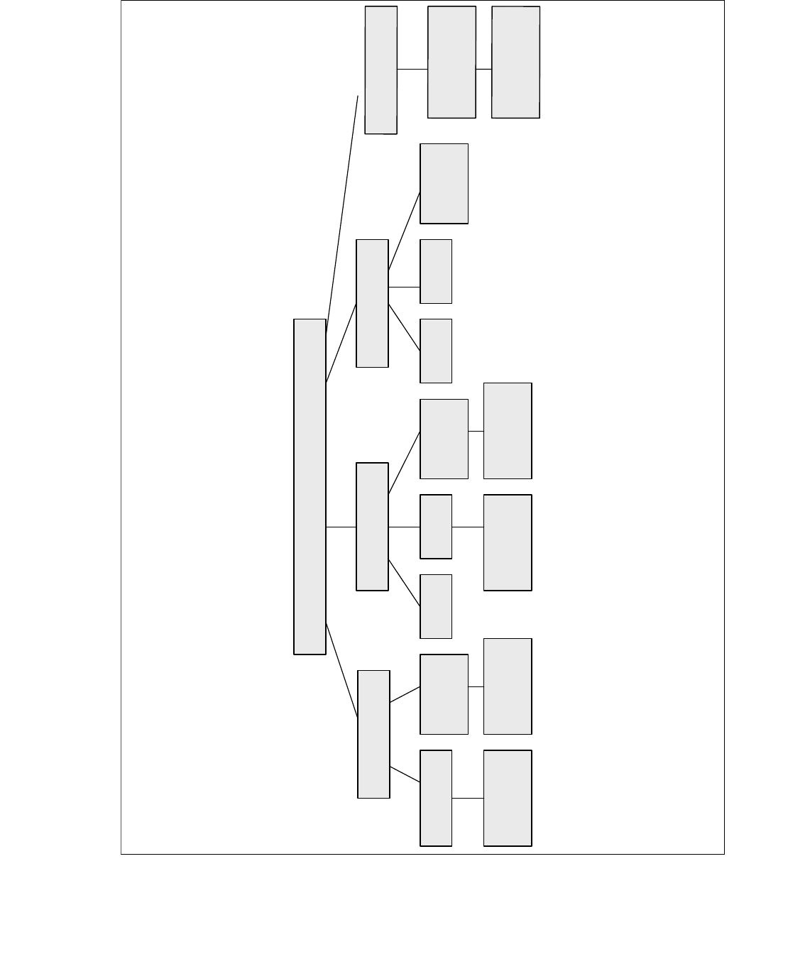
4.8 Overview of CAN Bus structures for X-series
X-serie
X2
X3 X4
Variant 1 Variant 2 Variant 1 Variant 2Only Variant 2
Variant 3
with CAN
Node
Variant 3 and
WPC 4
Variant 3 and
WPC 4
Variant 3
with CAN
Node
Variant 3
with CAN
Node
Variant 2 and
WPC 4
Variant 2 and
WPC 4
X
4
I
V
a
r
i
a
n
t
3
w
i
t
h
C
A
N
N
o
d
e
O
n
e
B
o
x
P
C
,
C
A
N
N
o
d
e
a
n
d
H
C
U
/
G
C
U
1 - 71
Edition 10/2018 SIPLACE CAN Bus
71
4.9 CAN Bus structure for SIPLACE X Machines
Attention: CAN Bus structure!
There are two operation diagrams: 00194418-02.pdf and 00194418-01.pdf.
Always use operation diagram 00194418-02 for X2 machines or 00195280-01.The differences be-
tween this two circuit diagrams is only the introduction of the Box PC and A364.
For X3 and X4 machines, either one of the two operation diagrams may be used for the CAN Bus
structure.
The CAN Bus terminating resistors are located near gantries on which a C&P head is installed on
the head interface (C500). Gantries with a Twin Head will have a terminating resistor directly in-
stalled on the adapter board.
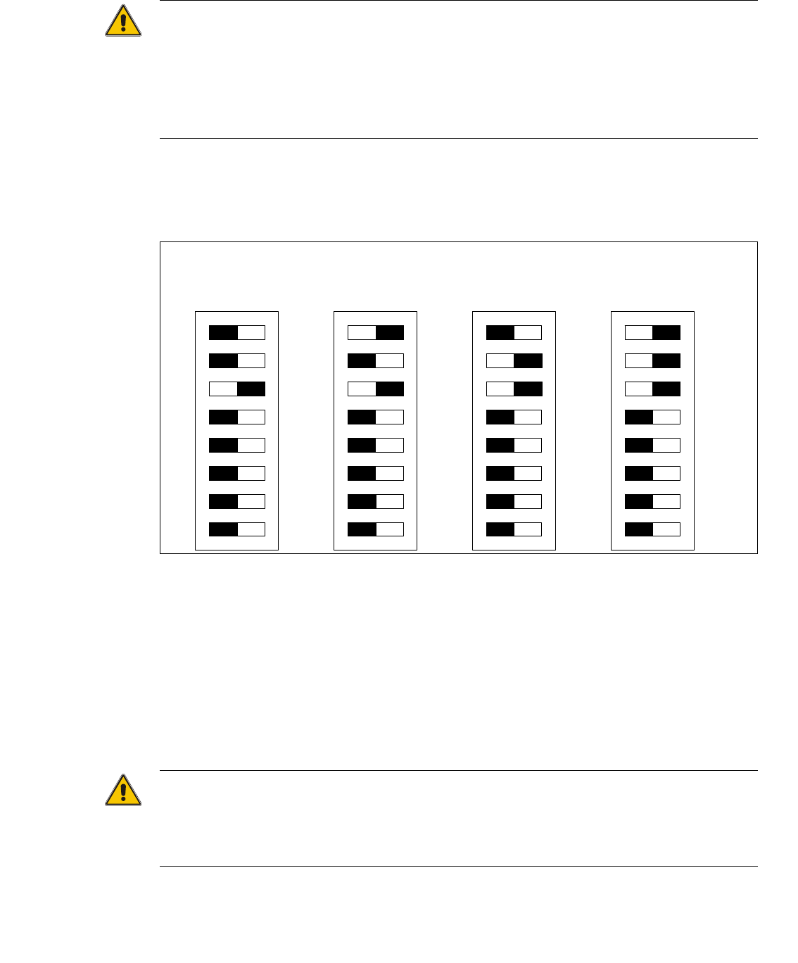
DIP switches configuration on the head interface (C500) with C&P heads
Key for DIP switches
Attention:
When using Head Modularity make sure that the terminating CAN resistor is set correctly. That
means, at the C&P heads switch CAN-Terminator ON and at the TWIN heads switch it OFF.
(DIP switch 3).
(1) P0 - Gantry address switch 1 (2) P1 - Gantry address switch 2
(3) CAN R - CAN terminator
(At TWIN-option always OFF)
(4) Boot - CAN Processor 16 Bit not mounted
(5) Reset - CAN Processor 16 Bit not mounted (6) C0 - CAN Address switch
(7) C1 - CAN Address switch (8) WPE - Write protect enable at the moment
OFF
DIP Switch
ON
78123456
ON
78123456
ON
78123456
ON
78123456
Ganty 1 Gantry 2 Gantry 3 Gantry 4
1 - 72
SIPLACE CAN Bus Edition 10/2018
72
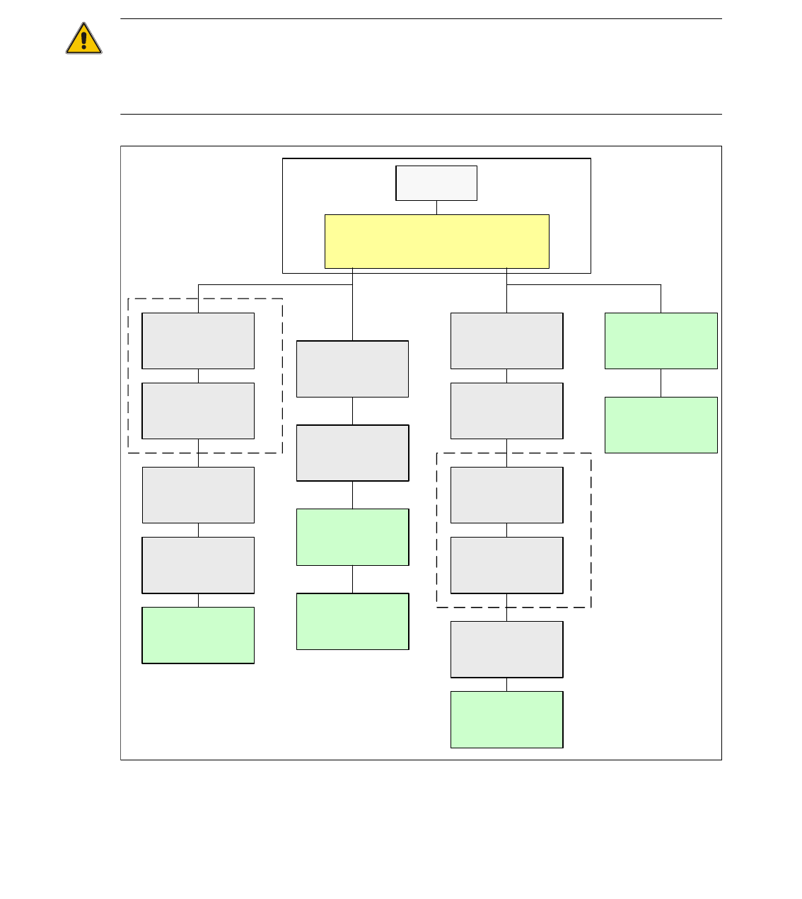
4.9.1 CAN Bus SIPLACE X2 (Variant 2)
The CAN Bus structure variant 01 for X2 machines was never delivered.
The vision control unit is only connected if you use an IC/FC camera version up to 03.
The IC/FC camera version upwards from 04 has the vision control unit in the camera and the cam-
era version 04 has its own CAN Bus connector.
Attention:
When you exchange a old stationary camera up to version 03 with a stationary camera
version 04, is it possible with a correct setting of the DIP switches to use the Vision Control unit in
the sectors. In this case the CAN Bus connector on the camera version 04 should not be used.
Fig. 4.9 - 1 CAN Bus structure X2 in line with operation diagram 00194418-02
SMP BUS
Computer Unit
C
O
M
U
n
i
t
1
6
8
CAN Bus cable
PA1
X6pn
Trailing Interface
Gantry 1
Transport
Control unit
COT 1
Tape cutter
(optional stat.
Camera vers.04)
CAN I/O
SUB Modul
Sector 4
Vision Control unit
only for stat.
Cameras up to
Vers.03
COT 4 / MTC2
Tape cutter
SUB Distributor Sector 4
Terminator
120 Ohm
Head board(C500)
Gantry 1
Terminator
(120 OHM)
CAN Bus cable
PA 2
X7pn
Main Distributor Sector 2
COT 3
Tape cutter
(optional stat.
Camera vers.04)
Axis unit
PA 2
(only Axes for PA2)
CAN I/O
Main Modul
Sector 2
COT 2 / MTC2
Tape cutter
Trailing Interface
Gantry 3
Terminator
120 Ohm
Head board(C500)
Gantry 3
Terminator
(120 OHM)
Axis unit
PA 2
(only Axes for PA1)
MC
Vision Control unit
only for stat.
Cameras up to
Vers.03