00194932-20 User Manual CAN Test Box-Error Frame Diagnostic unit_en.pdf - 第44页
1 - 44 SIPLACE CAN Bus Edition 10/2018 44 4.5 CAN Bus structure for HF 4.5.1 General Differences The HF machines will have the following differences: – Communication a ssemblies 2x KSP 352 or one KSP 354 – HF machines wi…
1 - 43
Edition 10/2018 SIPLACE CAN Bus
43
4.4 Overview of CAN Bus structures for HF and HF/3
HF
HF/3
Universal cable harnessOld cable harness
COM KSP354COM KSP 352
COM KSP 352 COM KSP354
SW 504 One
CAN bus per
machine
SW 505 One
CAN bus per
placement area
Version 01 Version 02
SW 504 One
CAN bus per
machine (was
not available)
SW 505 One
CAN bus per
placement area
COM KSP354COM KSP 352
SW 504 One
CAN bus per
machine
SW 505 One CAN
bus per placement
area (was not
available)
SW 505 One
CAN bus per
placement area
SW 504 One
CAN bus per
machine
Universal cable harnes
Version 02Version 01
Version 01 Version 02
1 - 44
SIPLACE CAN Bus Edition 10/2018
44
4.5 CAN Bus structure for HF
4.5.1 General Differences
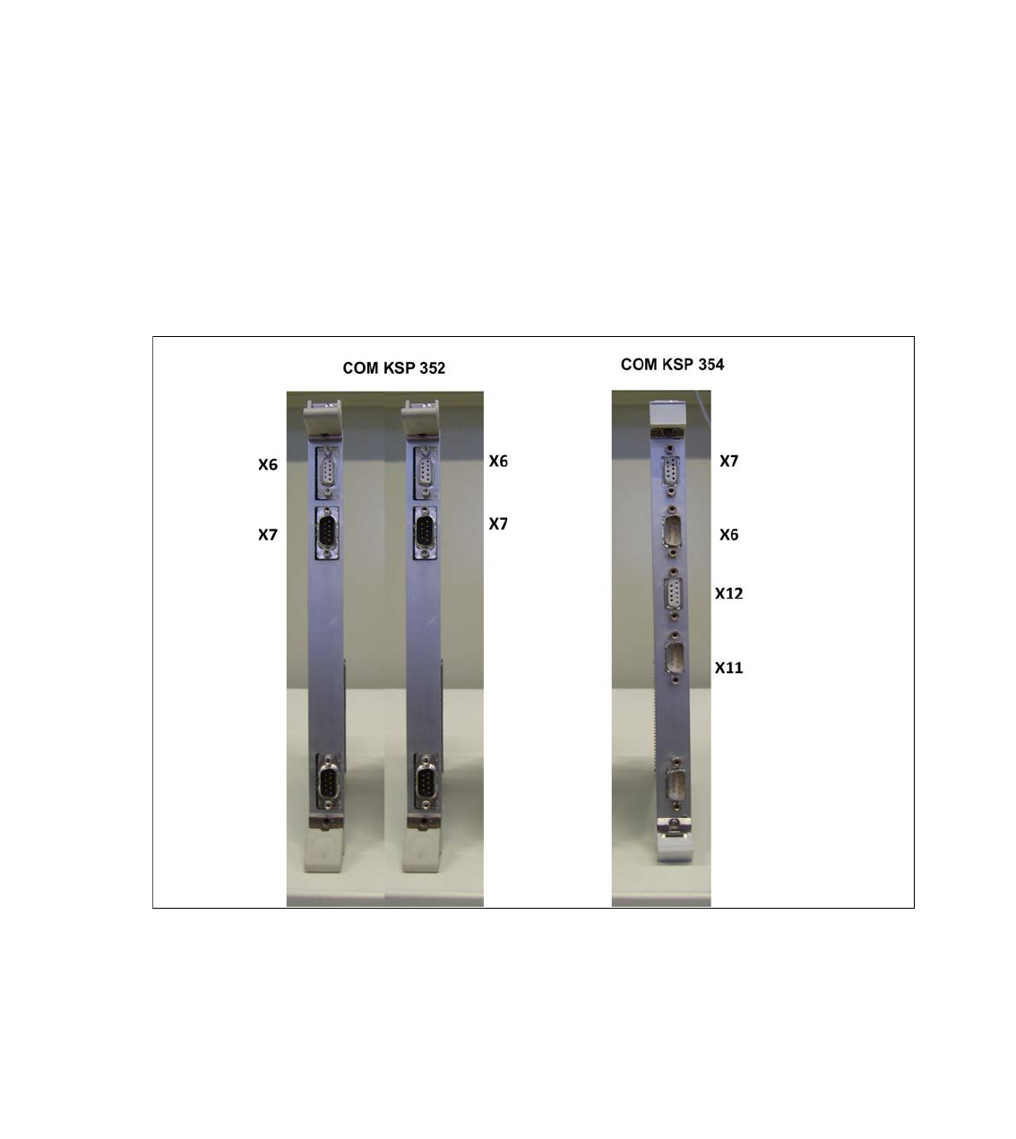
The HF machines will have the following differences:
– Communication assemblies 2x KSP 352 or one KSP 354
– HF machines with one CAN Bus for both placement areas are only supported by station soft-
ware versions 504.xx
– HF machines from station software version 505.xx only support the CAN Bus structure with
one CAN Bus per placement area.
– A difference is made between old and (new) universal cable harnesses.
This has the following consequences: 4
When checking or replacing the communication assemblies, always observe the terminating re-
sistors. Make sure you perform a physical check!
Fig. 4.5 - 1 KSP 352 and KSP 354 communication assemblies
1 - 45
Edition 10/2018 SIPLACE CAN Bus
45
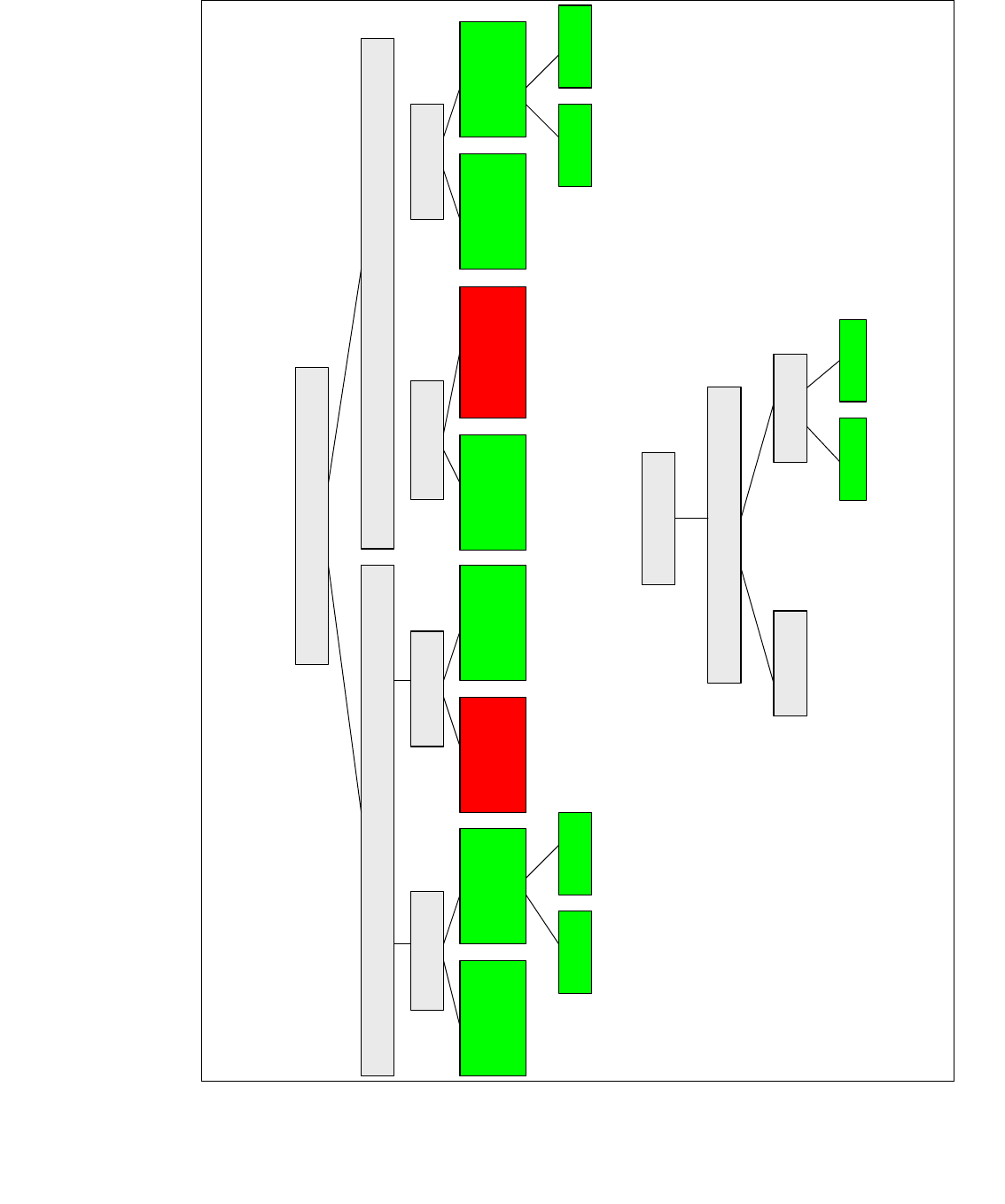
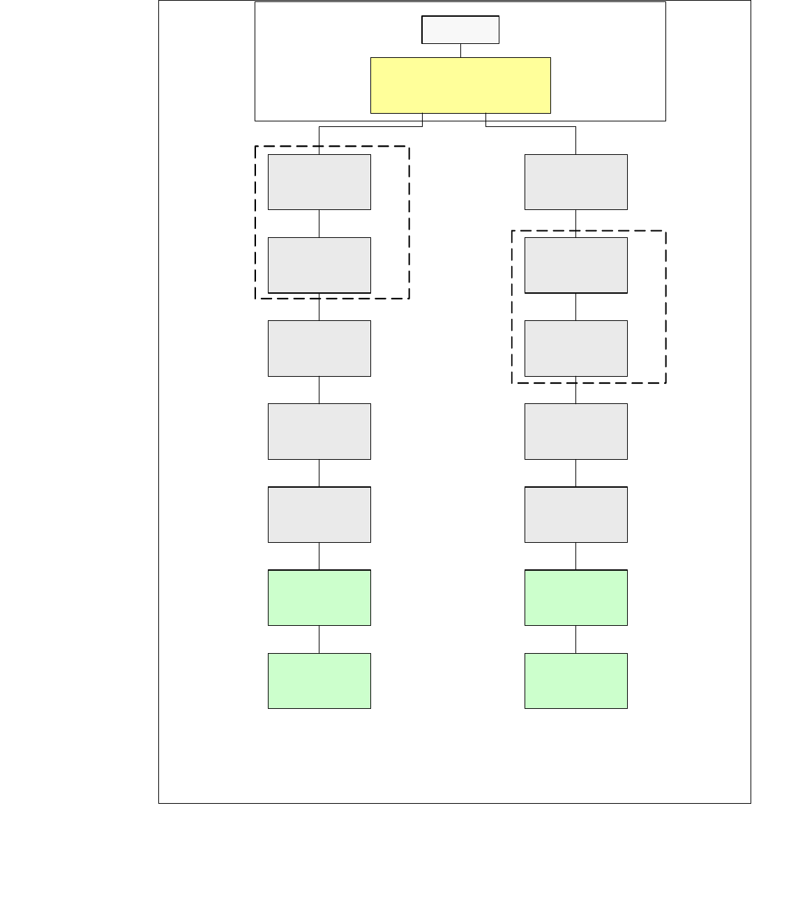
4.5.2 HF CAN Bus structures with old Cable Harness and KSP 352 (SW504)
CAN Bus structure with SW 504.xx and COM assembly KSP 352; with old cable harness (labeling
on cable = 0300xxxx-0x); one CAN Bus for both placement areas.
Fig. 4.5 - 2 HF CAN Bus structure (one CAN Bus with old cable harness, KSP 352 and SW 504)
SMP BUS
C
O
M
U
n
i
t
K
S
P
3
5
2
(
l
e
f
t
C
o
m
U
n
i
t
)
MC
Axis unit
PA 2
Trailing cable-
Interface
Gantry 1
Trailing cable-
Interface
Gantry 2 *
CAN Bus cable 2
CAN E/
A
Modu
l
Sektor
4
CAN E/
A
Modu
l
Sektor
4
CAN E/
A
Modu
l
Sektor
4
CAN I/O
SUB Module
Section 4
Vision
Section 2
COT 2 / MTC
Tape cutter
Transport
Control
unit
Vision
Control unit
CAN I/O
Main Module
COT 1
Tape cutter
COT 3
Tape cutter
COT 4 / MTC
Tape cutter
CAN Bus cable 1
Computer Unit
SUB Distributor Sector 2
Main Distributer Sector 4
Section 4
Control unit
Section 2
One CAN Bus !
* after SW Update 504 --> 505 Gantry 2 will be changed to
gantry 3 and two CAN Bus!
old Trailling cable
old circuit diagram!
x7pnx6pn
Head board(C500)
Gantry 1
Terminator
(120 OHM)
Head board(C500)
Gantry 2 *
Terminator
(120 OHM)