00194932-20 User Manual CAN Test Box-Error Frame Diagnostic unit_en.pdf - 第29页
1 - 29 Edition 10/2 018 SIPLACE CAN Bus 29 3 Error Frame Diagnostic unit The Error Frame Diagnosti c unit is a T ool which expands th e function of the SIPLACE CAN T est Box. This unit helps to locate Error Frames of the…
1 - 28
SIPLACE CAN Bus Edition 10/2018
28
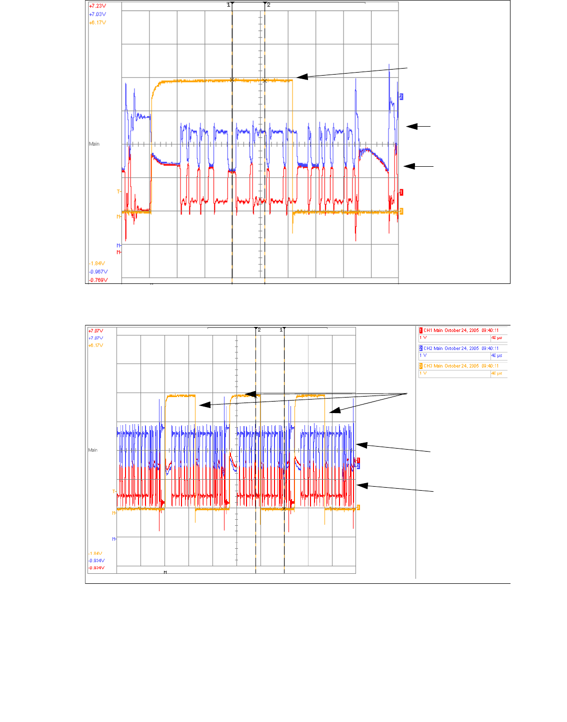
Fig. 2.8 - 8 CAN telegram with errors
Fig. 2.8 - 9 CAN telegram with errors
CAN _H level
CAN _L level
Error Frame Counter
CAN _H level
CAN _L level
Error Frame
Counter
1 - 29
Edition 10/2018 SIPLACE CAN Bus
29
3 Error Frame Diagnostic unit
The Error Frame Diagnostic unit is a Tool which expands the function of the SIPLACE CAN Test
Box. This unit helps to locate Error Frames of the machine CAN Bus.
The Error Frame Diagnostic unit is a Service tool and will also be use as CAN switch on the SI-
PLACE SX2 machine which are equipped with two WPC‘s. The function of the CAN switch in the
machine is to amplify the CAN Bus signal. Because the second WPC also communicate with the
CAN Bus the CAN Bus cable will be to long, so that the CAN commands will be corrupt or lost.
3.1 General
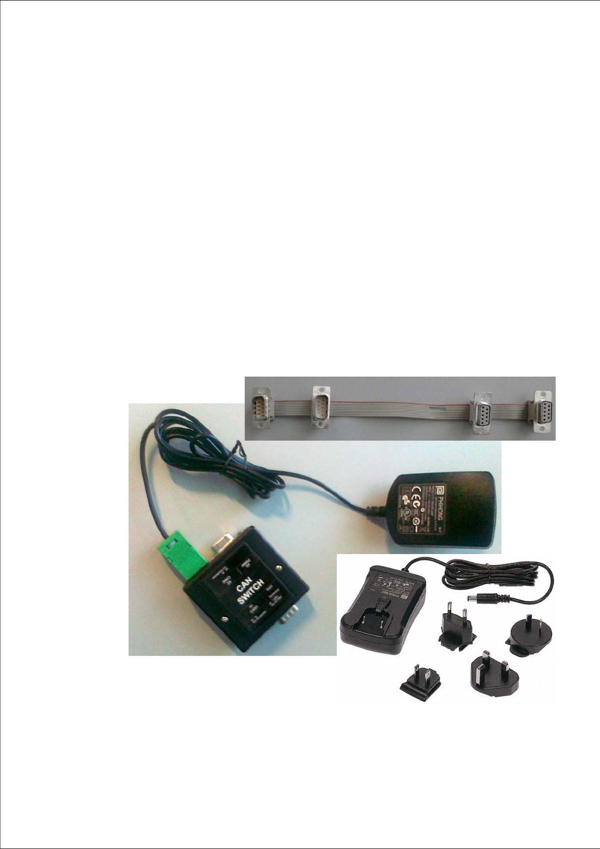
Ordernumber 03088404-xx - Diagnostic-Unit Errorframe
Content: - 03083844-xx CAN Switch
- 03088132-xx power supply with adapters
- 03089702-xx Adapter cable CAN Switch
Fig. 3.1 - 1 Error Frame Diagnostic unit 03088404-xx
1 - 30
SIPLACE CAN Bus Edition 10/2018
30
3.2 Function description
With the Siplace CAN Test Box we are able to recognize Error Frames on the machine CAN Bus.
The Error Frame will be shown on the display of the CAN Test Box. All subsystems of the machine
could send Error Frames, so it is helpful to know from which subsystem the Error frame comes.
With the Error Frame Diagnostic unit it is possible to determine the direction of the Error Frames.
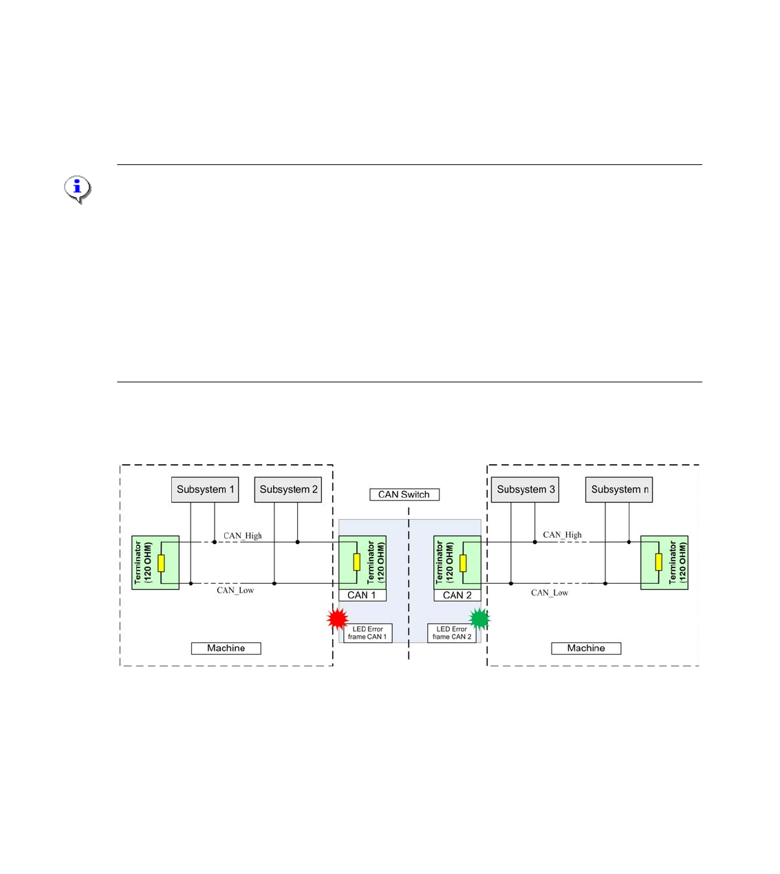
The CAN Switch will be split into two independent working CAN Bus networks.
The CAN commands will received on one side of the CAN Switch and forwarded to the other side.
The direction of communication is irrelevant. As long as the received CAN commands are not phy-
sically corrupted an green LED on each side of the CAN switch is activated. If one or more Error
Frames (depend of the dip-switch settings) are received, a red LED, left or right of the CAN switch
will show the direction of the incoming Error frames.
Note:
The transfer of CAN commands inside the CAN switch have a delay time of 150µs. When the CAN
Switch receive and transfer CAN commands from both sides, a delay time over 150µs may occur.
The result could be waiting times and reduction of the placement rate.
So therefore, please use the Service tool only for troubleshoting and remove the CAN Switch from
the machine CAN Bus after troubleshoting.
Exception for the second WPC on the SIPLACE SX2 machine and X- Series S machine only. On
the X-Series S machine we reduce the lenght of the CAN Bus cable with the CAN Switch to avoid
Error Frames, so the conveyor control unit and stationary cameras in PA 1 are disconnected from
the machine CAN Bus).
Principle: 3
Fig. 3.2 - 1 Function prinziple CAN Switch