00194932-20 User Manual CAN Test Box-Error Frame Diagnostic unit_en.pdf - 第34页
1 - 34 SIPLACE CAN Bus Edition 10/2018 34 With the follo wing settings on the DIP Switch S1.3-1.5 , the configura tion of the LE D status is pos- sible. That means, how many Erro r Frames have to be received, so that the…
1 - 33
Edition 10/2018 SIPLACE CAN Bus
33
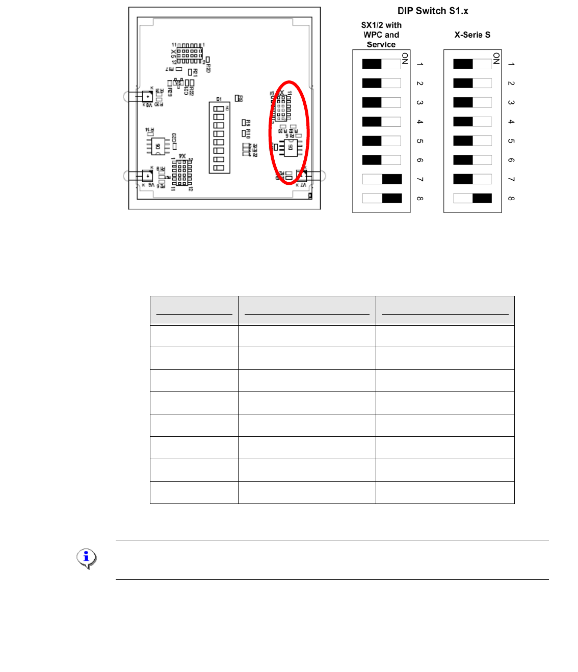
3.3.1 Settings on the DIP switch
To change the DIP switch settings, disconnect the CAN Switch from the power supply and open
the upper part (label) of the CAN switch by loosen the two screws.
Fig. 3.3 - 3 DIP- Switchr
Settings at the 8-fold DIP switch are possible:
Note:
The CAN Switch Box will be deliver with the DIP Switch settings of the X-Serie S machine.
DIP-switch S1 ON OFF
S1.1 Test mode normal mode
S1.2 500kBaud 1MBaud
S1.3 see table below see table below
S1.4 see table below see table below
S1.5 see table below see table below
S1.6 ASC Test ON ASC Test OFF
S1.7 120 Ohm CAN 1 no terminator
S1.8 120 Ohm CAN 2 no terminator
Tab. 3.3 - 1 DIP switch describtion S1
1 - 34
SIPLACE CAN Bus Edition 10/2018
34
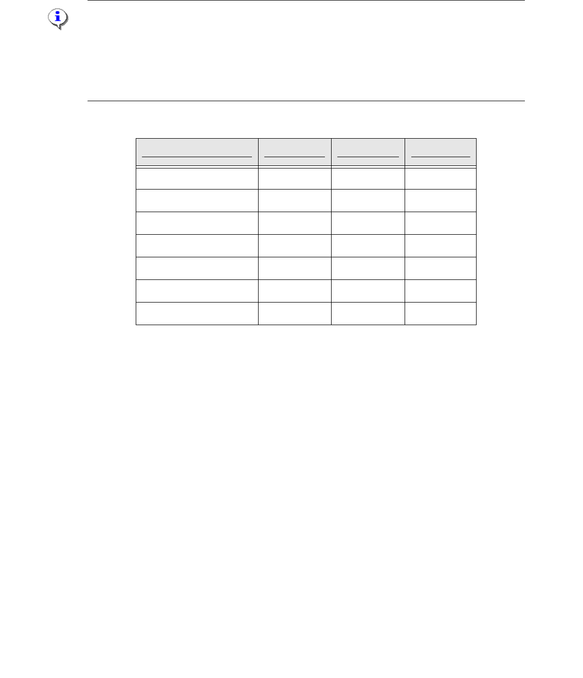
With the following settings on the DIP Switch S1.3-1.5, the configuration of the LED status is pos-
sible. That means, how many Error Frames have to be received, so that the LED status will be
change from green to red. The standard configuration is, that with each Error frames the status of
the LED will be change.
Note:
We recommended to keep the standard settings of the DIP switch S1.3 - S1.5. With this settings
it is possible to reset the red LED of the Error Frames manual with the RESET button. The quantity
of the Error Frames could you see on the CAN Test Box.
For all other settings of the DIP switch the red LED of the Error Frames will be reset automatically
after 10sec.
Fig. 3.3 - 4 LED Status Error Frames
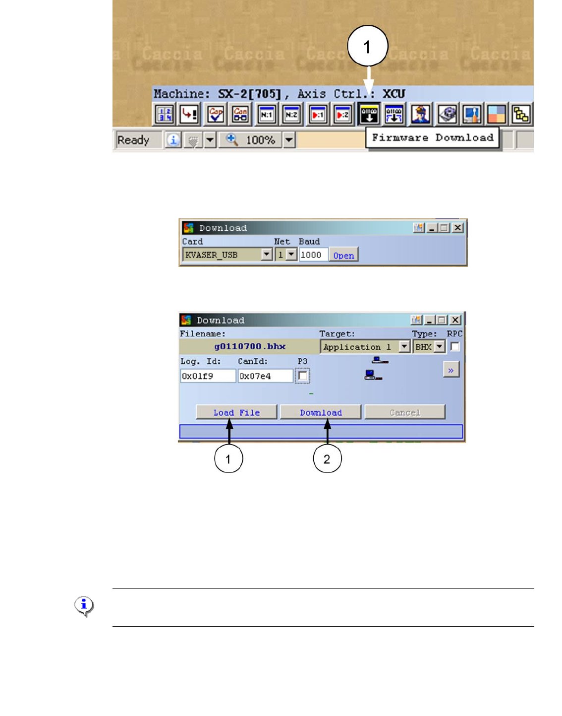
3.3.2 eSW Download on the CAN Switch
For a new eSW it is possible to download these with CACCIA to the CAN Switch.
The baud rate of 1Mbit on the Service laptop and on the CAN switch is necessary.
– - Connect the CAN Switch CAN1 and the Kvaser card canal 1 on the Service laptop via a
CAN Test cable.
– - Don‘t connect the power supply cable with the CAN switch!
– - Start CACCIA.
– - Open the Firmware Download window (1)
LED status S1.3 S1.4 S1.5
1 Error Frame OFF OFF OFF
5 Error Frames / Minute ON OFF OFF
10 Error Frames / Minute OFF ON OFF
10 Error Frames / hour ON ON OFF
50 Error Frames / hour OFF OFF ON
100 Error Frames / hour ON OFF ON
500 Error Frames / hour OFF ON ON
1 - 35
Edition 10/2018 SIPLACE CAN Bus
35
Fig. 3.3 - 5 Firmware Download
– Confirm the settings and press "Open".
Fig. 3.3 - 6 Settings Firmware Download
– - The following windows appears.
Fig. 3.3 - 7 Download Application 1
– - Write the CAN ID 0x7e4 of the CAN Switch Box into the field CanId:
– - Press the Button "Load File" and choose the download file.
– - Now, connect the power supply cable into the CAN switch and press within 3s the button
"Download".
Note:
The Download -Button have to press in the first 3s after switch on the CAN Switch!
– A confirmation of the succesful download appears.