00194932-20 User Manual CAN Test Box-Error Frame Diagnostic unit_en.pdf - 第111页
1 - 1 1 1 Edition 10/2 018 SIPLACE CAN Bus 111 4.12 CAN Bus structure SX / DX - Series (from MA No.N001/May 2015) All SX machine with serial number N001, de livered since may 2015 are provide d with new hard- ware: - Box…
1 - 110
SIPLACE CAN Bus Edition 10/2018
110
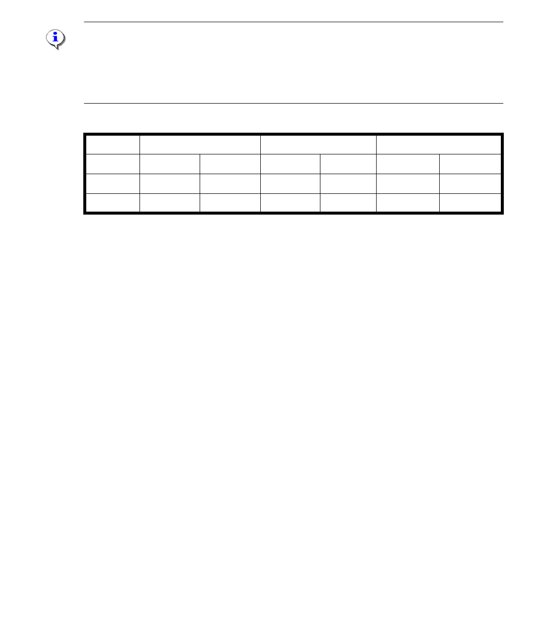
4.11.4 Measurement terminator (Resistor) on machine CAN Bus SX1/2
and DX1/2
On SX machines it is no longer possible to measure 60 Ohm between pin 2 and 7 on the CAN Bus
when the machine is switched off. At a switched-off machine with WPC or without WPC you have
to measure the following CAN resistance between pin 2 and pin 7.
Note:
With a configuration of an SIPLACE SX/DX machine and one WPC, the "PCB CAN-Bus-termina-
tor component table 03046863-xx" will be used. If there two WPC‘s installed, an additional retrofit
kit is necessary. The "Add-on kit COT-I30 CAN-Switch 2. WPC 03085518-xx" have to install on
both location, so you need two of this kits if you want to install an second WPC.
Checking the CAN Bus cable
Between pin 2 and 3 and between pin 7 and 3 there should be no connection
(approx. 1 to 3 MOhm ).
Attention: 4
Power fail signal is no longer in the CAN Bus cable. The Power fail signal is generated by the
25VDC Puls power supply unit and goes to the HCU and GCU directly.
without WPC 1x WPC connected 2x WPC connected
CAN1 CAN2 CAN1 CAN2 CAN1 CAN2
SX1/DX1 40 Ohm 60 Ohm 40 Ohm 40 Ohm -- --
SX2/DX2 30 Ohm 60 Ohm 30 Ohm 40 Ohm 30 Ohm 60 Ohm
1 - 111
Edition 10/2018 SIPLACE CAN Bus
111
4.12 CAN Bus structure SX / DX - Series (from MA
No.N001/May 2015)
All SX machine with serial number N001, delivered since may 2015 are provided with new hard-
ware:
- Box PC IBASE 402 (03120423-xx)
- CIN Box 4 fold CAN Bus card
- MGCU2 - Modulare Gantry Control Unit (Introduction of the 3-fold MGCU end of 2015)
- Power supply unit - Switched Mode Power Supply (SMPS)
- I/O Module 2
- changed trailling harness
With the introduction of the CAN Interface (03108598-xx CAN Interface CINX) the CAN structure
of the SX machine have not changed. Only the communication between the Station computer and
CIN Box is now via LAN cable, see describtion of the following pages.
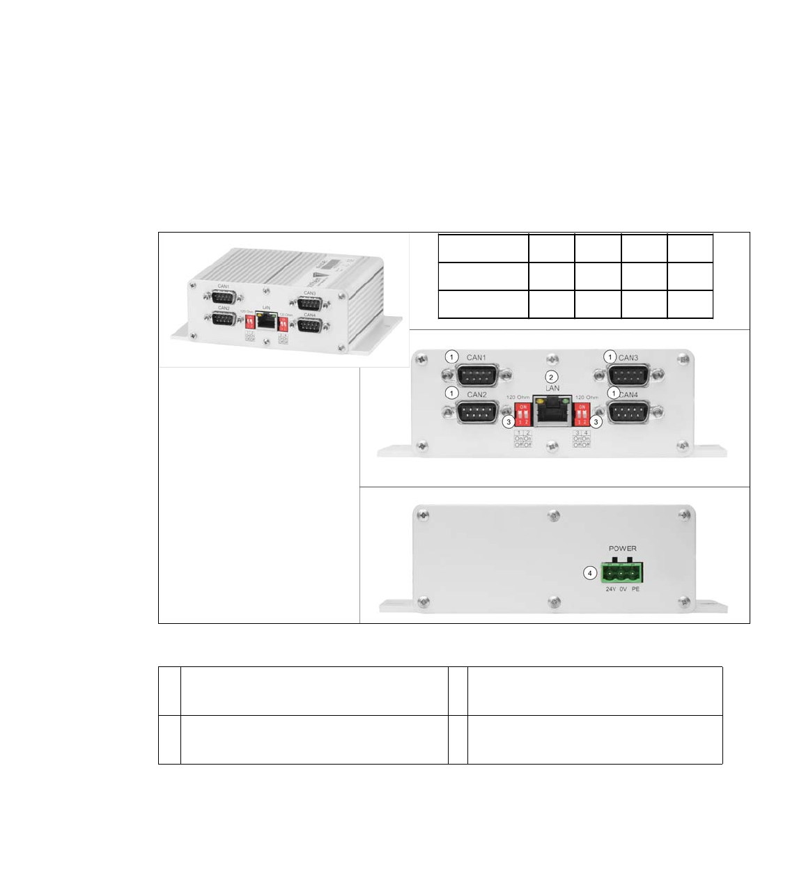
Fig. 4.12 - 1 03108598-xx CAN Interface CINX
1 CAN Bus Connector CAN1-4 (for SX ma-
chine CAN1 and CAN2 is used)
2 LAN Connector CAT 5 cable to PC-
LAN1
3 DIP Switch - setting the terminator of 120
Ohm for CAN1-4
4 Power connector 24V
1234
X-Series SONONONON
SX-Series OFF OFF OFF OFF
1 - 112
SIPLACE CAN Bus Edition 10/2018
112
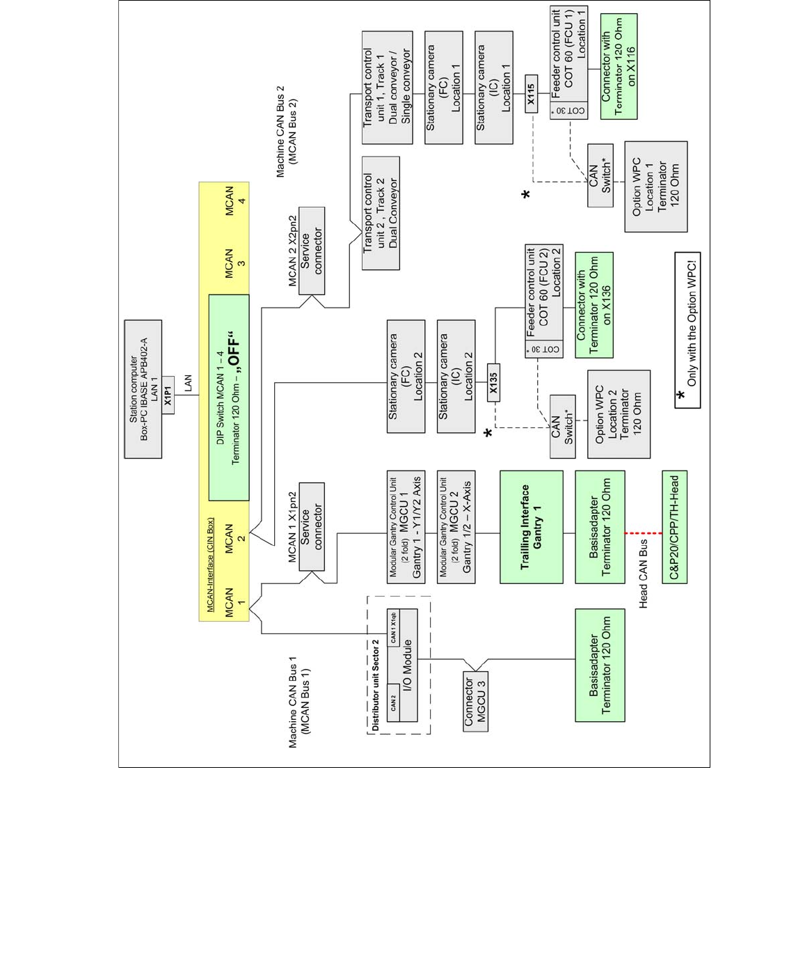
4.12.1 Machine CAN Bus structure SX1 / DX1 (from MA No.N001/May 2015)
Fig. 4.12 - 2 Machine CAN Bus structure SX/DX 1