00194932-20 User Manual CAN Test Box-Error Frame Diagnostic unit_en.pdf - 第165页
1 - 165 Edition 10/2 018 SIPLACE CAN Bus 165 4.20.1 Machine CAN Bus Structure TX2i, TX2 V ersion 2 The SIPLACE TX V2 machines use 4 machine CAN bus networks for communication to the sub- systems. T o check the CAN bus ne…
1 - 164
SIPLACE CAN Bus Edition 10/2018
164
4.20 CAN Bus structure SIPLACE TX-Series Version 2
With the further development of the TX series (version 2) and the introduction of the SLIM FCU
on the COT insert, as well as the FCU (feeder control unit), a changed CAN bus structure results
between the subsystems.
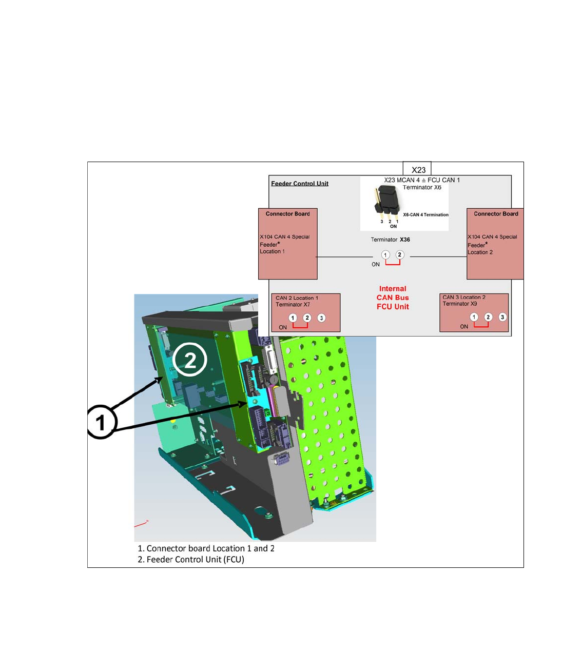
The FCU is directly supplied with data via the CIN Box of the MCAN 4 as a subsystem. It consists
of one FCU board and one connection module each for the location 1 and 2
.
The FCU unit works with 4 independent CAN bus channels, which must be equipped with 120
Ohm terminating resistors, jumper setting on the FCU board..
FCU CAN Bus 1: MCAN 4 from the CIN Box - Terminator Jumper X6
FCU CAN Bus 2: Feeder CAN Bus location 1 with feeder, feeder unlock device, tape cutter, sen-
sor reject bin, nozzle changer, valve lock and unlock COT and nozzle station
FCU CAN Bus 3: Feeder CAN Bus Stellplatz 2 with feeder, feeder unlock device, tape cutter, sen-
sor reject bin, nozzle changer, valve lock and unlock COT and nozzle station
FCU CAN Bus 4: Special Feeder (JTF-ML2) - terminator Jumper X36
Fig. 4.20 - 1 CAN Bus connection FCU unit SIPLACE TX V2
1 - 165
Edition 10/2018 SIPLACE CAN Bus
165
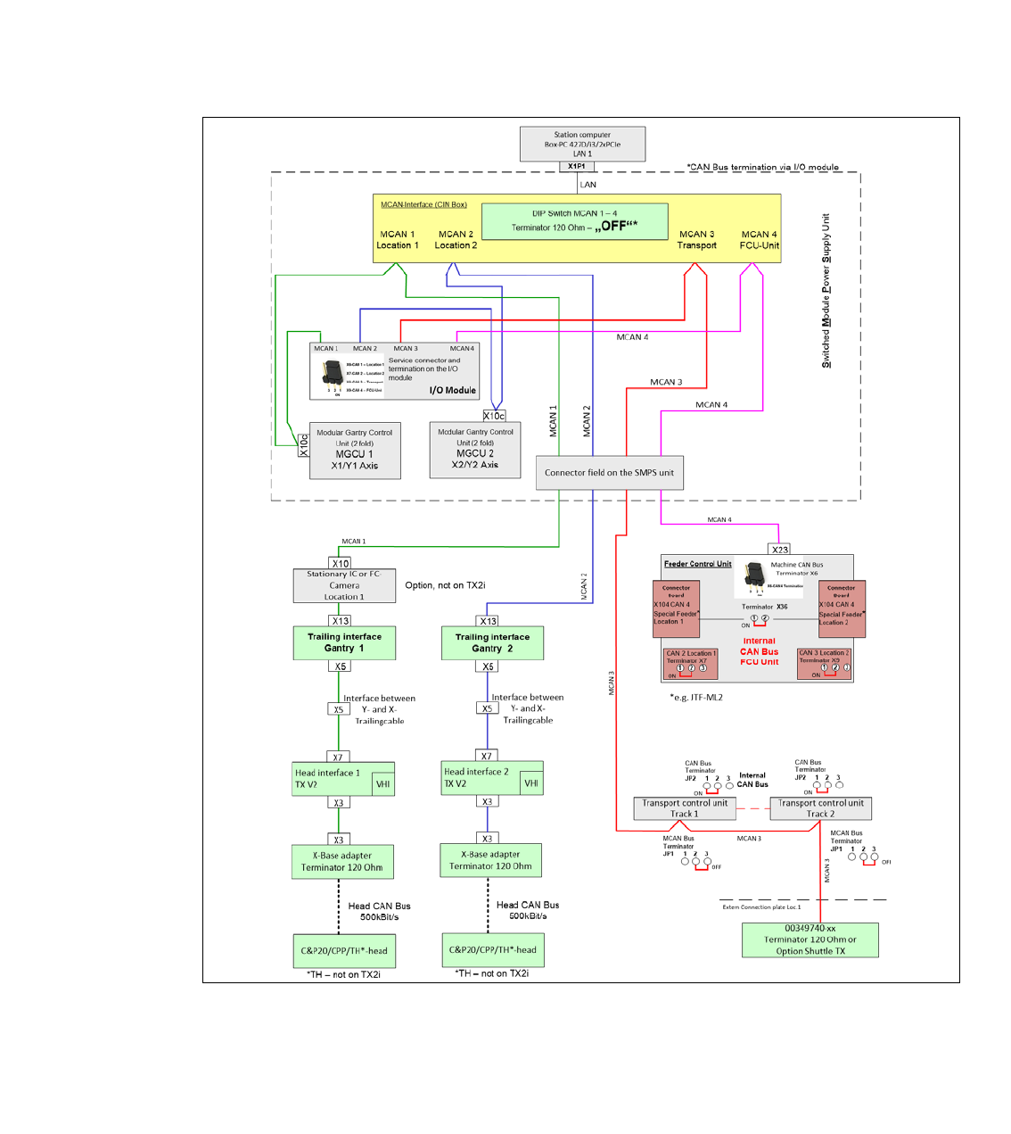
4.20.1 Machine CAN Bus Structure TX2i, TX2 Version 2
The SIPLACE TX V2 machines use 4 machine CAN bus networks for communication to the sub-
systems. To check the CAN bus networks, there are new service connectors (10pin male connec-
tor, no SUB-D connector) on the I / O module. Use the CAN bus test cable 03159250-0.
The following overview shows the assignment of the subsystems to the CAN bus networks.
MCAN 1 for the stationary camera at position 1, MGCU 1, Portal 1
MCAN 2 MGCU 2, Portal 2)
MCAN 3 transport control with the option Shuttle extension TX.
MCAN 4 FCU Unit.
Fig. 4.20 - 2 Machine CAN Bus SIPLACE TX2i and TX2 V2
1 - 166
SIPLACE CAN Bus Edition 10/2018
166
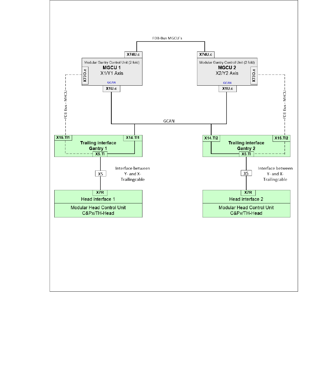
4.20.2 Gantry CAN Bus TX2i/2 Version 2
The GCAN-Bus is responsible for the communication between the Modular Gantry Control Unit‘s
(MGCU´s) and the Modular Head Control Units (MHCU‘s) for gantries in one placement area (e.g.
Head-CAN-Diagnose or SIRIO-communication).
Fig. 4.20 - 3 Gantry CAN Bus SIPLACE TX2i/2 V2