00195813-05_IM_SSW_605.03_SP1_DE EN.pdf - 第16页
Installation Manual, Station Software Version 605.03 SP1 07/2011 Edition 16 of 48 4.2.3 Vision computer (optional) Name SIMATIC Box PC 627 CPU / clock frequency Pentium M / 2 GHz RAM 1 GB Hard disk 40 GB External DVD dri…

Installation Manual, Station Software Version 605.03 SP1 07/2011 Edition
15 of 48
4.2.2 Machine controller
Name
SMP16-CPU076
CPU / clock frequency
Celeron / 650 MHz
RAM
256 MB
Hard disk
40 GB
External DVD drive
No
Floppy drive
3.5", 1.44 MB
USB interfaces
and external USB hub
Yes
Network
1 x 10/100Base-T
Table 4-4: Machine controller hardware (previous configuration of SIPLACE X-series)
Name
SMP16-CPU086
CPU / clock frequency
Intel M / 1600 MHz
RAM
256 MB
Hard disk
40 GB
External DVD drive
No
USB interfaces
and external USB hub
Yes
Network
1 x 10/100Base-T
Table 4-5: Machine controller hardware (previous configuration of SIPLACE X-series and SIPLACE D3)
Name
SIMATIC Box PC 627
CPU / clock frequency
Pentium M / 2 GHz
RAM
1 GB
Hard disk
40 GB
External DVD drive
Yes
Serial interfaces
1
USB interfaces
and external USB hub
Yes
Network
2x 100 MBit
Table 4-6: Machine controller hardware (current configuration of SIPLACE X-series and SIPLACE D3)

Installation Manual, Station Software Version 605.03 SP1 07/2011 Edition
16 of 48
4.2.3 Vision computer (optional)
Name
SIMATIC Box PC 627
CPU / clock frequency
Pentium M / 2 GHz
RAM
1 GB
Hard disk
40 GB
External DVD drive
Yes
Serial interfaces
1
USB interfaces and external USB hub
Yes
Network
2x 100 MBit
Table 4-7: Vision computer hardware (optional for SIPLACE X2 and X3 with 3D coplanarity sensor)
Installation Manual, Station Software Version 605.03 SP1 07/2011 Edition
4.3 SIPLACE D1, D2 and D4 hardware components
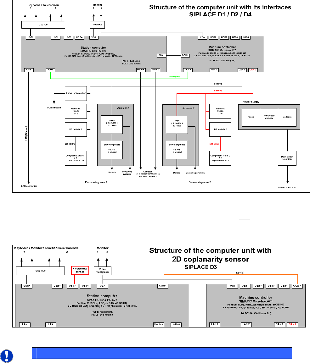
The following diagram shows the hardware components of the computer system for the D-series machine
types (except SIPLACE D3) in two-computer operation:
Fig. 4-2: Hardware components of the computer system for the SIPLACE D-series except SIPLACE D3 (schematic block diagram)
The following diagram shows the hardware components for the computer system with a configured
coplanarity sensor:
Fig. 4-3: Hardware components of the computer system for the SIPLACE D3 with 2D coplanarity sensor - schematic block diagram
NOTICE
The machine computer and Vision computer software can optionally be used in one-
computer operation on a Box PC 627B.
17 of 48