TM3355.CheckNozzleBuffingFunctionSpecifications.pdf - 第21页
Y AMAHA M otor Co. Ltd ., IM Company SMT Software Engineering Grou p MDOC-SOFT50 052 21 /27 The height when grounding it b y the grounding chec k by the vacuum is set. The am ount of the of fset to Measurement height (mm…
YAMAHA Motor Co. Ltd.,
IM Company
SMT Software Engineering Group
MDOC-SOFT50052
20/27
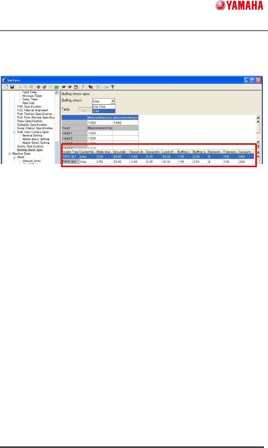
(2) Detail Parameter Setting
It is possible to set parameters of nozzle buffing check operation for each nozzle.
You can use this function with initial setting of the parameters. When you change a nozzle to
a new type of nozzle, you need to confirm its figure and modify the parameters if necessary.
Nozzle type
The nozzle kind corresponding to a set each line is displayed.
Current level check
Setting the "execute" or "not execute" for load check with current level of Z-axis motor.
If the current value is unstable, the abnormalities of a nozzle may be incorrect-detected.
When such a case occurs frequently, it can avoid by supposing this setup " not execute".
Slide down speed (%)
Setting the slide down speed for load check with servo buffing.
If the execution speed is too quick, the abnormalities of a nozzle may be incorrect-detected.
This setup is changed, when such a case occurs frequently, or when gathering the
execution speed of a nozzle buffing check.
Grounding down speed (%)
Setting the speed when grounding down for grounding check with vacuum.
If the execution speed is too quick, the abnormalities of a nozzle may be incorrect-detected.
This setup is changed, when such a case occurs frequently, or when gathering the
execution speed of a nozzle buffing check.
Speed change height (mm)
The height that changes into grounding down speed (%) because of the grounding check by
the vacuum is set.
The amount of the offset to Measurement height (mm) is set.
When the structure of a nozzle is changed, the suitable value suitable for the nozzle is set
up.
Grounding height (mm)

YAMAHA Motor Co. Ltd.,
IM Company
SMT Software Engineering Group
MDOC-SOFT50052
21/27
The height when grounding it by the grounding check by the vacuum is set.
The amount of the offset to Measurement height (mm) is set.
When the structure of a nozzle is changed, the suitable value suitable for the nozzle is set
up.
Load of harden check (N)
The load when press-in it by the load check by the servo buffing is set.
When the structure of a nozzle is changed, the suitable value suitable for the nozzle is set
up.
Buffing check approach stroke (mm)
The stroke that ascent before it press-in by the load check by the servo buffing is set.
The amount of the offset to Measurement height (mm) is set.
When the structure of a nozzle is changed, the suitable value suitable for the nozzle is set
up.
Buffing stroke (mm)
The amount press-in by the load check by the servo buffing is set.
The amount of press-in from buffing check approach stroke (mm) is set.
When the structure of a nozzle is changed, the suitable value suitable for the nozzle is set
up.
Sampling count
The number of samples when the current difference is calculated by the load check by the
value of the current of Z-axis motor is set.
Tolerance of the current difference
The permissible value of the current difference is set by the load check by the value of the
current of Z-axis motor.
When the structure of a nozzle is changed, the suitable value suitable for the nozzle is set
up.
Although accuracy goes up by increasing the number of samplings, the execution speed of
a check falls.
Vacuum check timer (msec)
The timer of the following vacuum waiting of vacuum ON is set.
If time is taken until a vacuum is stabilized, the abnormalities of a nozzle may be
incorrect-detected.
This setup is changed, when such a case occurs frequently, or when gathering the
execution speed of a check.
YAMAHA Motor Co. Ltd.,
IM Company
SMT Software Engineering Group
MDOC-SOFT50052
22/27
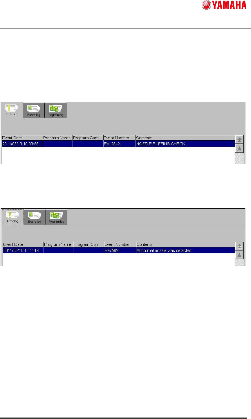
7.3. Output log
After the nozzle buffing check is executed, the execution result is output to [MIS]-[Error log].
The detection result is output in case of normal or abnormal. (See Fig. 0.2)
Moreover, when the detection result is abnormality, the station numbers of the nozzle with the
error can be displayed up to ten.
Log output when normality finish.
Fig. 0.1 Error log screen normality finish
Log output when abnormality finish.
Fig. 0.2 Error log screen abnormality finish