111.pdf - 第17页
Machine Automa tion Controller NX1P 17 Electrical and Mechan ical Specifications *1. Includes the End Cover, and does not include projecting parts. *2. Includes the End Cover. The weight of the End Cover is 82 g. *3. Inc…
Machine Automation Controller NX1P
16
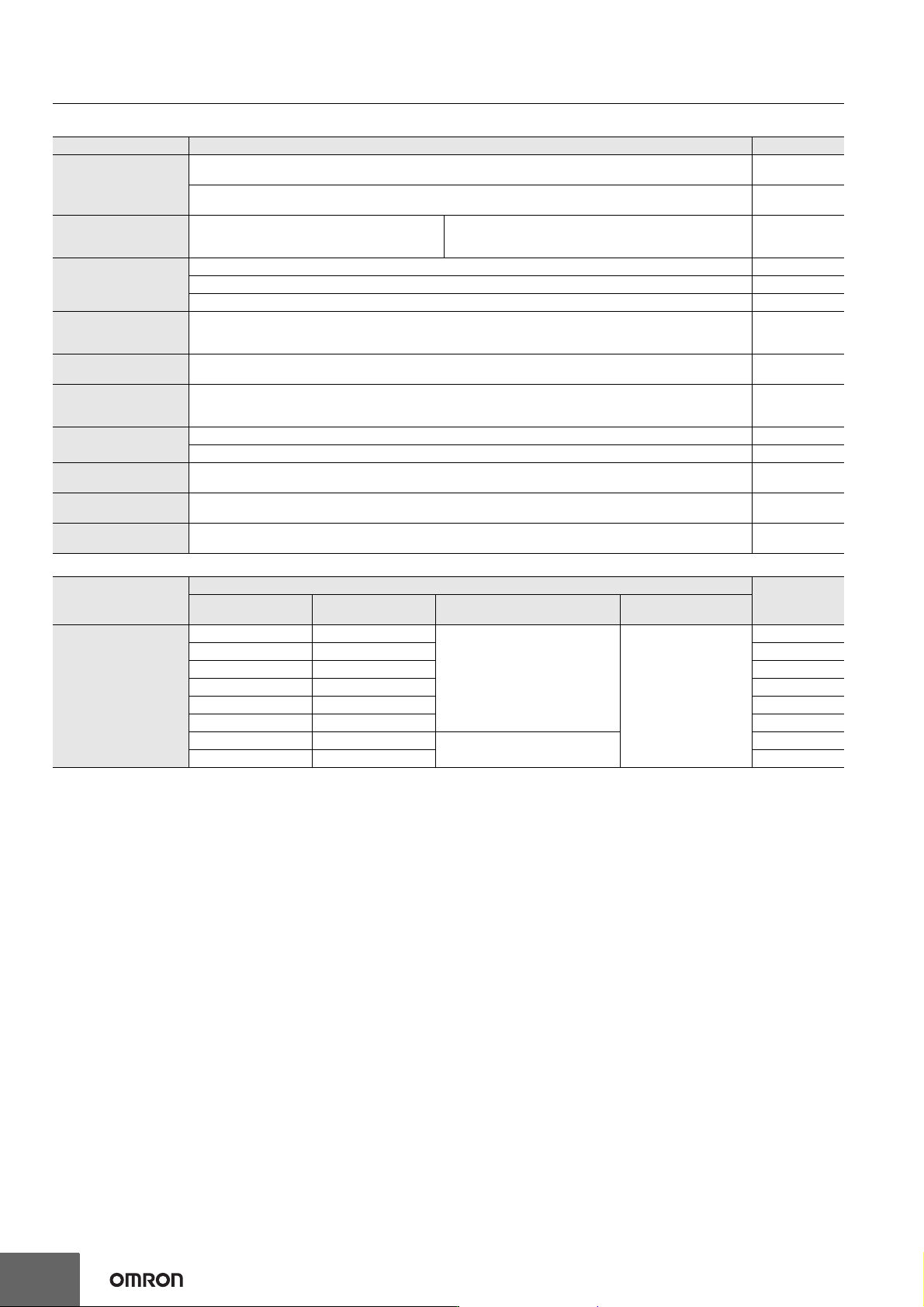
Optional Products/Maintenance Products/DIN Track Accessories
*1. EtherCAT junction slaves cannot be used for EtherNet/IP and Ethernet.
*2. Industrial switching hubs cannot be used for EtherCAT.
*3. There are restrictions on the combination of CPU Unit version and memory card. Refer to NJ/NX-series CPU Unit Software User's Manual
(W501) 8-5-2 Specifications of Supported SD Memory Cards, Folders, and Files for details.
*4. Use the NX-END02 End Cover only for the CPU Unit and the NX-END01 End Cover only for the EtherCAT Coupler Unit.
Product Name Specification Model
EtherCAT junction
slaves *1
3 ports. Power supply voltage: 20.4 to 28.8 VDC (24 VDC -15 to +20%).
Current consumption (A): 0.08
GX-JC03
6 ports. Power supply voltage: 20.4 to 28.8 VDC (24 VDC -15 to +20%).
Current consumption (A): 0.17
GX-JC06
Industrial Switching
Hubs for EtherNet/IP and
Ethernet *2
Quality of Service (QoS):
EtherNet/IP control data priority
10/100BASE-TX, Auto-Negotiation
5 ports. Current consumption (A): 0.07
Power supply connector included.
W4S1-05D
Memory Cards *3
SD memory card, 2 GB HMC-SD292
SDHC memory card, 4 GB HMC-SD492
SDHC memory card, 16GB HMC-SD1A2
Battery
The battery is not mounted when the product is shipped.
To turn OFF the power supply to the equipment for a certain period of time by using the clock data for programming,
event logs, etc., you need a separately-sold battery to retain the clock data. Refer to the Battery page for details.
CJ1W-BAT01
End Cover
(For NX1P2 CPU Unit) *4
Must be connected to the right end of the CPU Rack.
One End Cover is provided with the CPU Unit.
NX-END02
End Cover
(For EtherCAT Coupler
Unit) *4
One End Cover is provided with the EtherCAT Coupler Unit. NX-END01
DIN Tracks
Length: 0.5 m; Height: 7.3 mm PFP-50N
Length: 1 m; Height: 7.3 mm PFP-100N
End Plate
There are 2 stoppers provided with CPU Units and I/O Interface Units as standard accessories to secure the Units on
the DIN Track.
PFP-M
Unit/Terminal Block
Coding Pins
For 10 Units
(Terminal Block: 30 pins, Unit: 30 pins)
NX-AUX02
DIN Track Insulation
Spacers
A Spacer to insulate the control panel from the DIN Track.
To insulate the EtherCAT Slave Terminal from the control panel, use Din Track Insulation Spacers.
NX-AUX01
Product Name
Specification
Model
No. of terminals
Terminal number
indications
Ground terminal mark
Terminal current
capacity
Terminal Blocks
8A/B
None
10 A
NX-TBA082
12 A/B NX-TBA122
16 A/B NX-TBA162
16 C/D NX-TBB162
12 C/D NX-TBB122
16 C/D NX-TBB162
8A/B
Provided
NX-TBC082
16 A/B NX-TBC162
Machine Automation Controller NX1P
17
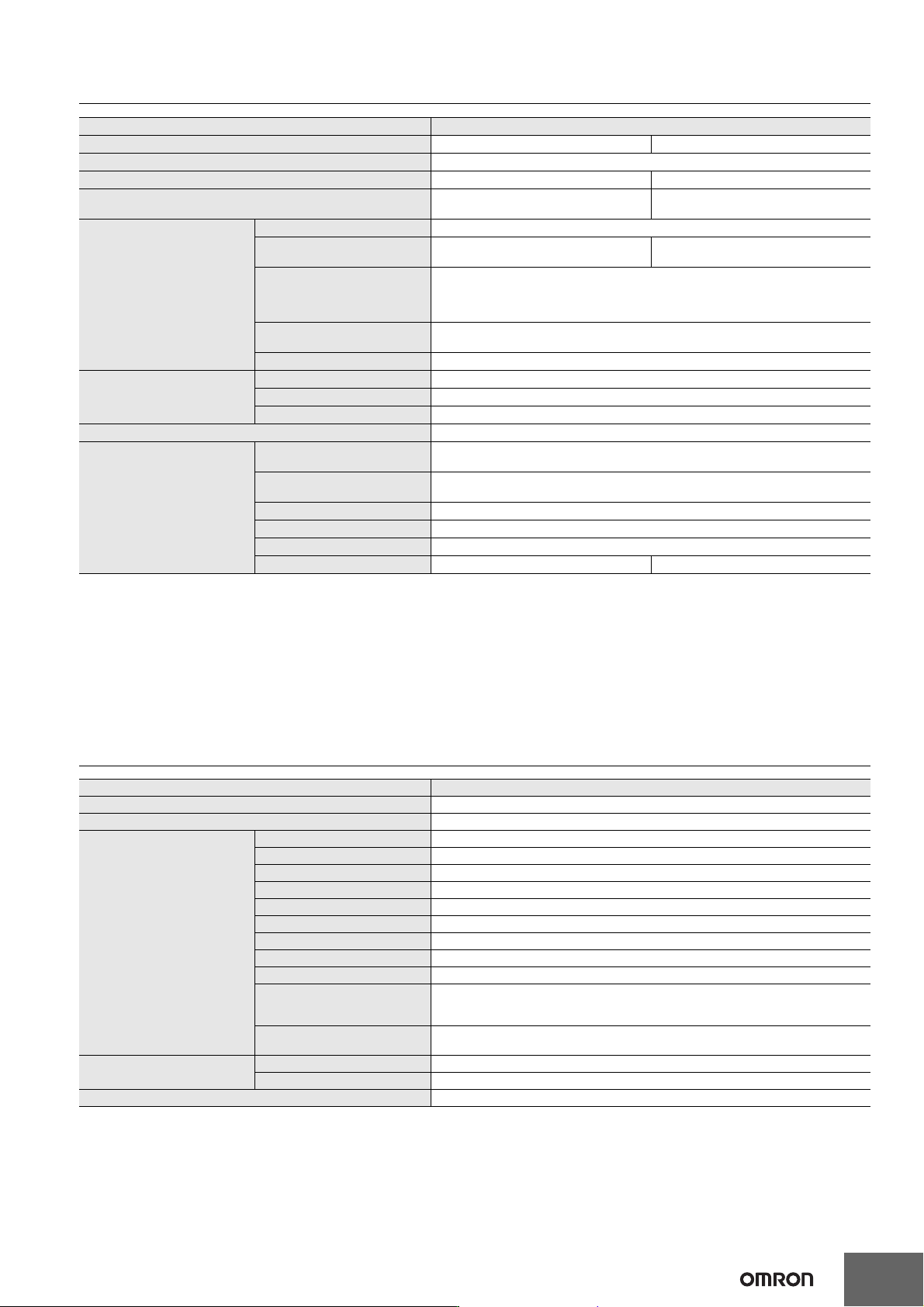
Electrical and Mechanical Specifications
*1. Includes the End Cover, and does not include projecting parts.
*2. Includes the End Cover. The weight of the End Cover is 82 g.
*3. Includes the SD Memory Card and Option Board. The NX Unit power consumption to NX Units is not included.
*4. The inrush current may vary depending on the operating condition and other conditions. Therefore, select fuses, breakers, and external power
supply devices that have enough margin in characteristic and capacity, considering the condition under which the devices are used.
*5. The amount of current that can be passed constantly through the terminal. Do no exceed this current value when you use a through-wiring for
the Unit power supply.
*6. When the type of the I/O power supply to NX Units you use is the supply from NX bus, an Additional I/O Power Supply Unit is required. The
maximum I/O power supply current from an Additional I/O Power Supply Unit is 4 A. Refer to the NX-series NX1P2 CPU Unit Hardware User’s
Manual (Cat. No. W578) for details.
General Specifications
*1. Refer to the OMRON website (https://www.ia.omron.com/) or consult your OMRON representative for the most recent applicable standards for
each model.
Item Specification
Model NX1P2-140DT NX1P2-9024DT
Enclosure Mounted in a panel
Dimensions (mm) *1 154 × 100 × 71 mm (W×H×D) 130 × 100 × 71 mm (W×H×D)
Weight *2
NX1P2-140DT: 650 g
NX1P2-140DT1: 660 g
NX1P2-9024DT: 590 g
NX1P2-9024DT1: 590 g
Unit power supply
Power supply voltage 24 VDC (20.4 to 28.8 VDC)
Unit power consumption *3
NX1P2-140DT: 7.05 W
NX1P2-140DT1: 6.85 W
NX1P2-9024DT: 6.70 W
NX1P2-9024DT1: 6.40 W
Inrush current *4
For cold start at room temperature:
10 A max./0.1 ms max.
and
2.5 A max./150 ms max.
Current capacity of power
supply terminal *5
4 A max.
Isolation method No isolation: between the Unit power supply terminal and internal circuit
Power supply to the NX Unit
power supply
NX Unit power supply capacity 10 W max.
NX Unit power supply efficiency 80 %
Isolation method No isolation: between the Unit power supply terminal and NX Unit power supply
I/O Power Supply to NX Units Not provided *6
External connection terminals
Communication connector
RJ45 for EtherNet/IP Communications × 1
RJ45 for EtherCAT Communications × 1
Screwless clamping terminal
block
For Unit power supply input, grounding, and input signal: 1 (Removable)
For output signal: 1 (Removable)
Output terminal (service supply) Not provided
RUN output terminal Not provided
NX bus connector 8 NX Units can be connected
Option board slot 21
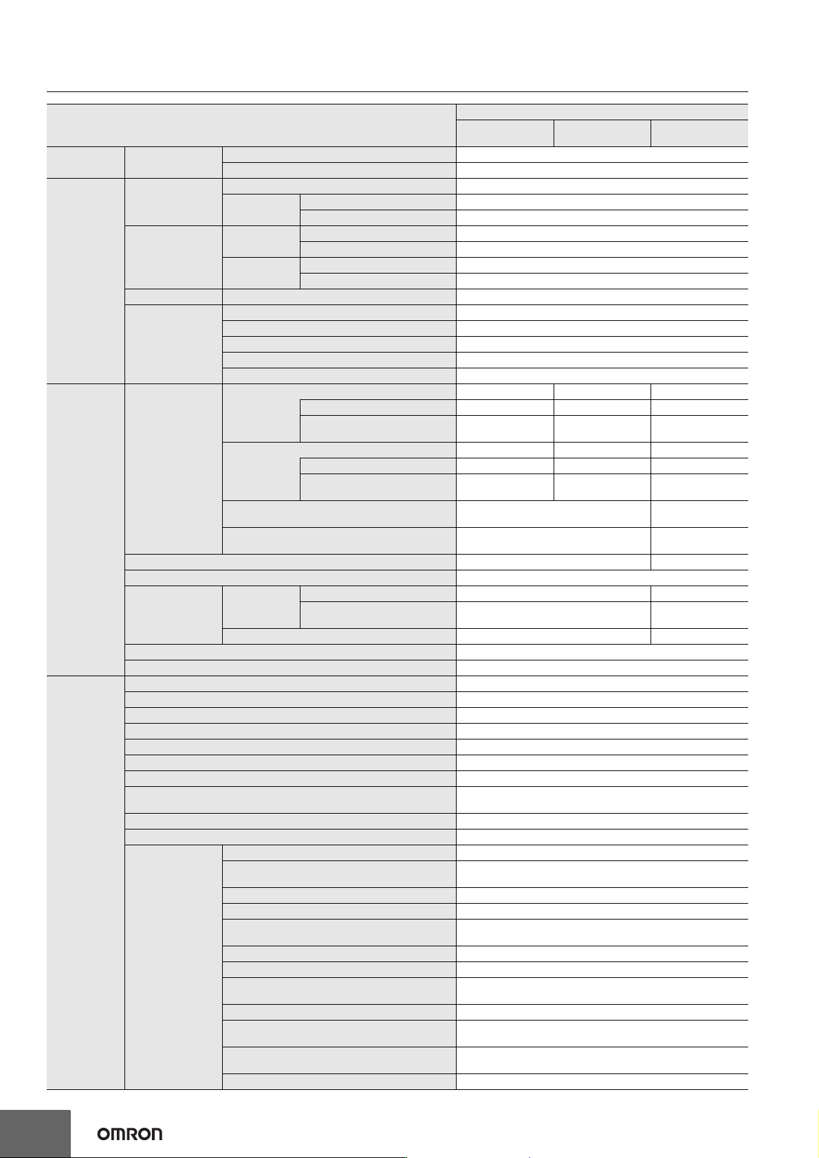
Item Specification
Enclosure Mounted in a panel
Grounding method Ground to less than 100 Ω.
Operating environment
Ambient operating temperature 0 to 55°C
Ambient operating humidity 10% to 95% (with no condensation)
Atmosphere Must be free from corrosive gases.
Ambient storage temperature -25 to 70°C (excluding battery)
Altitude 2,000 m max.
Pollution degree 2 or less: Meets IEC 61010-2-201.
Noise immunity 2 kV on power supply line (Conforms to IEC 61000-4-4.)
Overvoltage category Category II: Meets IEC 61010-2-201.
EMC immunity level Zone B
Vibration resistance
Conforms to IEC 60068-2-6.
5 to 8.4 Hz with 3.5-mm amplitude, 8.4 to 150 Hz, acceleration of 9.8 m/s
2
100 min each in X, Y, and Z directions (10 sweeps of 10 min each = 100 min total)
Shock resistance
Conforms to IEC 60068-2-27.
147 m/s
2
, 3 times in X, Y, and Z directions
Battery
Life 5 years (Power ON time rate 0% (power OFF))
Model CJ1W-BAT01 (sold separately)
Applicable standards *1 cULus, EU, UKCA, RCM, KC, NK, LR
Machine Automation Controller NX1P
18
Performance Specifications
Item
NX1P2-
11/
111
10/
101
90/
901
Processing
time
Instruction
execution times
LD instruction 3.3 ns
Math instructions (for long real data) 70 ns or more
Programming
Program capacity
*1
Size 1.5 MB
Quantity
Number of POU definitions 450
Number of POU Instances 1,800
Memory capacity
for variables *2
Retain
attributes
Size 32 kB
Number of variables 5,000
No Retain
attributes
Size 2 MB
Number of variables 90,000
Data types Number of data types 1,000
Memory for CJ-
series Units (Can
be specified with
AT specifications
for variables.)
CIO Area 0 to 6,144 channel (0 to 6,143) *3
Work Area 0 to 512 channel (W0 to W511) *3
Holding Area 0 to 1,536 channel (H0 to H1,535) *4
DM Area 0 to 16,000 channel (D0 to F15,999) *4
EM Area ---
Motion control
Number of
controlled axes *5
Maximum number of controlled axes 12 axes 10 axes 4 axes
Motion control axes 8 axes 6 axes ---
Single-axis position control
axes
4 axes 4 axes 4 axes
Maximum number of used real axes 8 axes 6 axes 4 axes
Used motion control servo axes 4 axes 2 axes ---
Used single-axis position
control servo axes
4 axes 4 axes 4 axes
Maximum number of axes for linear interpolation
axis control
4 axes per axes group ---
Number of axes for circular interpolation axis
control
2 axes per axes group ---
Maximum number of axes groups 8 axes groups ---
Motion control period Same as the period for primary periodic task
Cams
Number of cam
data points
Maximum points per cam table 65,535 points ---
Maximum points for all cam
tables
262,140 points ---
Maximum number of cam tables 80 tables ---
Position units Pulse, mm, μm, nm, degree, and inch
Override factors 0.00% or 0.01% to 500.00%
Built-in
EtherNet/IP
port
Number of ports 1
Physical layer 10BASE-T, 100BASE-TX
Frame length 1,514 bytes max.
Media access method CSMA/CD
Modulation Baseband
Topology Star
Baud rate 100 Mbps/s (100BASE-TX)
Transmission media
STP (shielded, twisted-pair) cable of Ethernet category 5, 5e or
higher
Maximum transmission distance between Ethernet switch and node 100 m
Maximum number of cascade connections There are no restrictions if an Ethernet switch is used.
CIP service: Tag
data links (cyclic
communications)
Maximum number of connections 32
Packet interval *6
Can be set for each connection.
2 to 10,000 ms in 1-ms increments
Permissible communications band 3,000 pps *7 (including heartbeat)
Maximum number of tag sets 32
Tag types
Network variables
CIO/WR/HR/DM
Number of tags per connection (i.e., per tag set) 8 (7 tags if Controller status is included in the tag set.)
Maximum number of tags 256
Maximum link data size per node
(total size for all tags)
19,200 bytes
Maximum data size per connection 600 bytes
Maximum number of registrable tag sets
32
(1 connection = 1 tag set)
Maximum tag set size
600 bytes
(Two bytes are used if Controller status is included in the tag set.)
Multi-cast packet filter *8 Supported.