111.pdf - 第25页
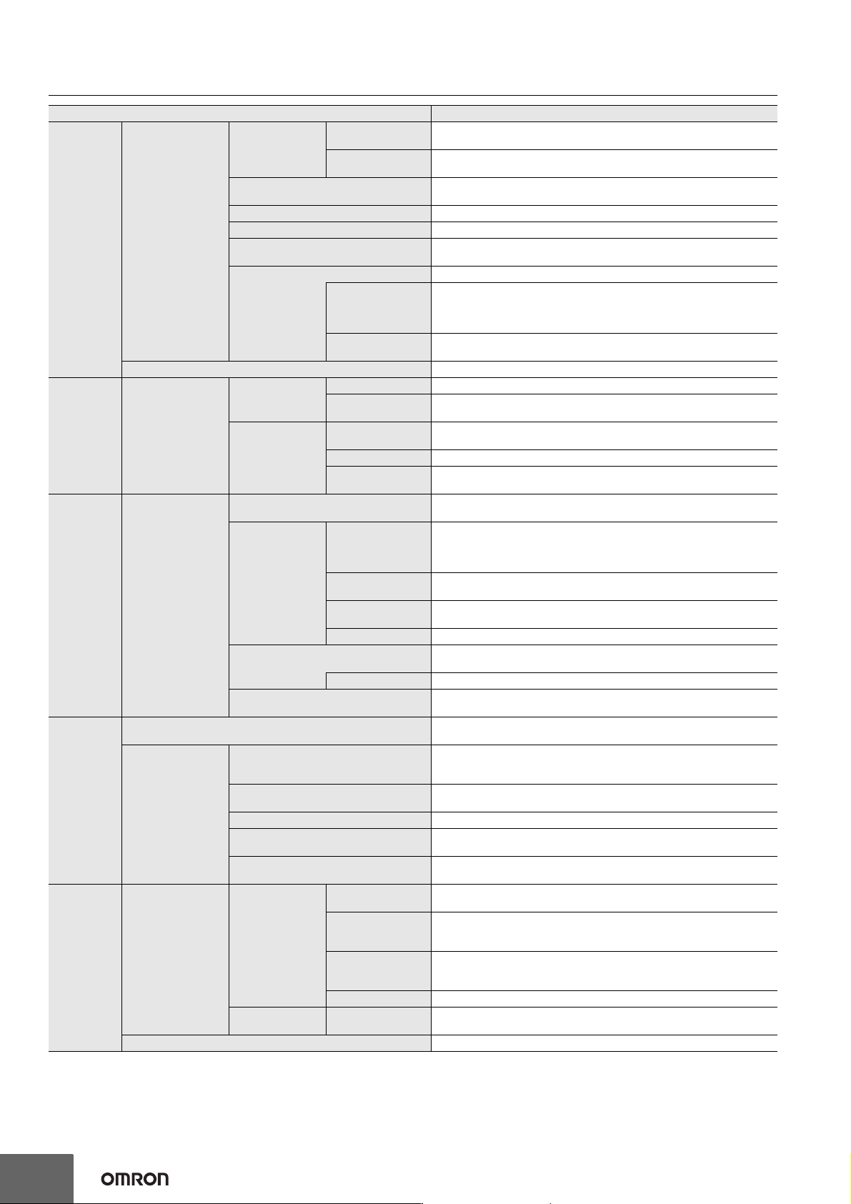
Machine Automa tion Controller NX1P 25 Input Terminal Block Terminal Arrangement The description is given for each CPU Unit model. NX1P2-1 40DT NX1P2-9024DT Symbol Terminal name Description Reference Functional gro…
Machine Automation Controller NX1P
24
*1. Inline ST is supported. (Inline ST is ST that is written as an element in a ladder diagram.)
*2. This is the total of 512 events for the CPU Unit and 64 events for the NX Unit.
*3. This is the total of 512 events for the CPU Unit and 16 events for the NX Unit.
*4. Restore is supported with unit version 1.14 or later.
Debugging
Data Tracing
Types
Single Triggered
Trace
When the trigger condition is met, the specified number of samples are taken
and then tracing stops automatically.
Continuous Trace
Data tracing is executed continuously and the trace data is collected by the
Sysmac Studio.
Maximum Number of Simultaneous Data
Traces
2
Maximum Number of Records 10000
Maximum Number of Sampled Variables 48 variables
Timing of Sampling
Sampling is performed for the specified task period, at the specified time, or
when a sampling instruction is executed.
Triggered Traces Trigger conditions are set to record data before and after an event.
Trigger Conditions
When BOOL variable changes to TRUE or FALSE
Comparison of non-BOOL variable with a constant
Comparison Method: Equals (=), Greater than (>), Greater than or
equals (≥), Less Than (<), Less than or equals (≤), Not equal (≠)
Delay
Trigger position setting: A slider is used to set the percentage of sampling
before and after the trigger condition is met.
Simulation The operation of the CPU Unit is emulated in the Sysmac Studio.
Reliability
functions
Self-Diagnosis
Controller Errors
Levels Major faults, partial faults, minor faults, observation, and information
Maximum number of
message languages
9 (Sysmac Studio)
2 (NS-series PT)
User-defined
Errors
Function
User-defined errors are registered in advance and then records are created
by executing instructions.
Levels 8
Maximum number of
message languages
9
Security
Protecting Software
Assets and
Preventing
Operating Mistakes
CPU Unit Names and Serial IDs
When going online to a CPU Unit from the Sysmac Studio, the CPU Unit name
in the project is compared to the name of the CPU Unit being connected to.
Protection
User Program
Transfer with no
Restoration
Information
You can prevent reading data in the CPU Unit from the Sysmac Studio.
CPU Unit Write
Protection
You can prevent writing data to the CPU Unit from the Sysmac Studio or SD
Memory Card.
Overall Project File
Protection
You can use passwords to protect .smc files from unauthorized opening on
the Sysmac Studio.
Data Protection You can use passwords to protect POUs on the Sysmac Studio.
Verification of Operation Authority
Online operations can be restricted by operation rights to prevent damage to
equipment or injuries that may be caused by operating mistakes.
Number of Groups 5
Verification of User Program Execution ID
The user program cannot be executed without entering a user program
execution ID from the Sysmac Studio for the specific hardware (CPU Unit).
SD Memory
Card
functions
Storage Type
SD Memory Card,
SDHC Memory Card
Application
Automatic Transfer from SD Memory
Card
When the power supply to the Controller is turned ON, the data that is stored
in the autoload directory of the SD Memory Card is transferred to the
Controller.
Program transfer from SD Memory Card
With the specification of the system-defined variable, you can transfer a
program that is stored in the SD Memory Card to the Controller.
SD Memory Card Operation Instructions You can access SD Memory Cards from instructions in the user program.
File Operations from the Sysmac Studio
You can perform file operations for Controller files in the SD Memory Card and
read/write general-purpose document files on the computer.
SD Memory Card Life Expiration
Detection
Notification of the expiration of the life of the SD Memory Card is provided in
a system-defined variable and event log.
Backing up
data
SD Memory Card
backups
Operating
methods
CPU Unit front panel
DIP switch
Backup, verification, and restoration operations are performed by
manipulating the front-panel DIP switch on the CPU Unit.
Specification with
system-defined
variables
Backup, verification, and restoration operations are performed by
manipulating system-defined variables.*4
SD Memory Card
Window in Sysmac
Studio
Backup and verification operations are performed from the SD Memory Card
Window of the Sysmac Studio.
Special instruction The special instruction is used to backup data.
Protection
Disabling backups
to SD Memory Cards
Backing up data to a SD Memory Card is prohibited.
Sysmac Studio Controller backups The Sysmac Studio is used to backup, restore, or verify Controller data.
Item NX1P2
Machine Automation Controller NX1P
25
Input Terminal Block
Terminal Arrangement
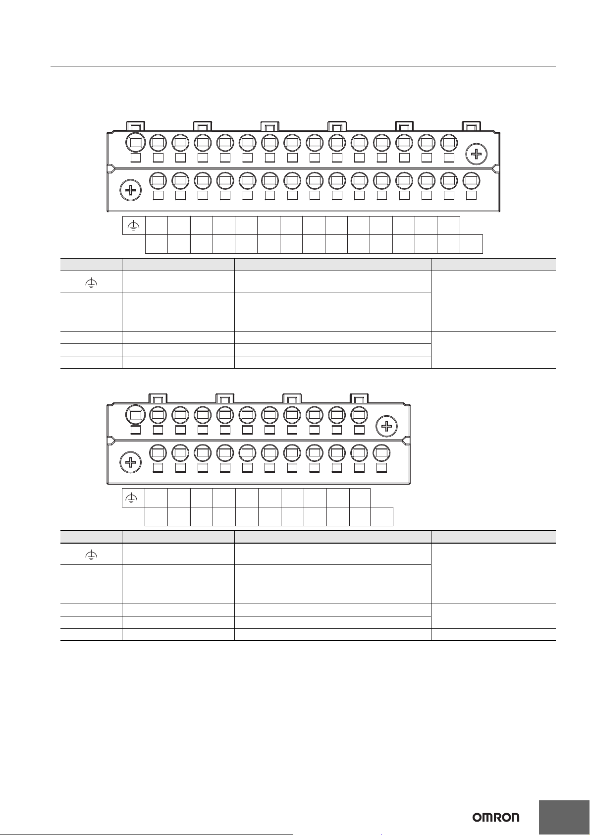
The description is given for each CPU Unit model.
NX1P2-140DT
NX1P2-9024DT
Symbol Terminal name Description Reference
Functional ground terminal
The functional ground terminal. Connect the ground
wire to the terminal.
Refer to the NX-series NX1P2
CPU Unit Hardware User’s
Manual (Cat. No. W578) for
details.
+/- Unit power supply terminals
These terminals are connected to the Unit power
supply.
The + terminals and - terminals are internally
connected to each other.
COM Common terminal Common terminal for the input circuits
Refer to the Input Specifications
page.
00 to 15 Input terminals General-purpose input A
16 to 23 Input terminals General-purpose input B
Symbol Terminal name Description Reference
Functional ground terminal
The functional ground terminal. Connect the ground
wire to the terminal.
Refer to the NX-series NX1P2
CPU Unit Hardware User’s
Manual (Cat. No. W578) for
details.
+/- Unit power supply terminals
These terminals are connected to the Unit power
supply.
The + terminals and - terminals are internally
connected to each other.
COM Common terminal Common terminal for the input circuits
Refer to the Input Specifications
page.
00 to 13 Input terminals General-purpose input A
NC NC Do not connect anything. ---
+-
-+
COM
00
17
18
15
16
13
14
11
12
09
10
07
08
05
06
03
04
01
02
19
20
21
22 23
NC
13
NC
11
12
09
10
07
08
05
06
03
04
01
02
COM
00
-
-
+
+
Machine Automation Controller NX1P
26
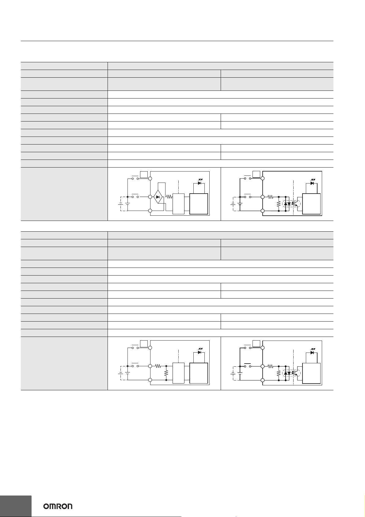
Input Specifications
The specifications depends on the input terminal numbers of the model. *1
*1. The following specifications apply to models with lot number 18321M (products produced in March 2021) or earlier.
*2. These values are the fixed response time needed by the hardware. A value from 0 to 32 ms (default: 1 ms) that is set on the Support Software
is added to these values.
*3. Set the filter time for every 4 points.
Item Specification
Input type General-purpose input A General-purpose input B
Input terminal number
NX1P2-140DT: 00 to 15
NX1P2-9024DT: 00 to 13
NX1P2-140DT: 16 to 23
NX1P2-9024DT: None
Internal I/O common For both NPN/PNP
Input voltage 24 VDC (15 to 28.8 VDC)
Connected sensor Two-wire or three-wire sensors
Input impedance −−− 4.3 kΩ
Input current 4.22 mA 5.3 mA typical
ON voltage 15 VDC min.
OFF voltage/current 5 VDC max./1 mA max.
ON response time *2 2.5 µs max. 1 ms max.
OFF response time *2 2.5 µs max. 1 ms max.
ON/OFF filter time *3 No filter, 0.25 ms, 0.5 ms, 1 ms (default), 2 ms, 4 ms, 8 ms, 16 ms, 32 ms, 64 ms, 128 ms, 256 ms
Circuit configuration
Item Specification
Input type General-purpose input A General-purpose input B
Input terminal number
NX1P2-140DT: 00 to 15
NX1P2-9024DT: 00 to 13
NX1P2-140DT: 16 to 23
NX1P2-9024DT: None
Internal I/O common For both NPN/PNP
Input voltage 24 VDC (15 to 28.8 VDC)
Connected sensor Two-wire or three-wire sensors
Input impedance 4.0 kΩ 4.3 kΩ
Input current 5.8 mA typical 5.3 mA typical
ON voltage 15 VDC min.
OFF voltage/current 5 VDC max./1 mA max.
ON response time *2 2.5 µs max. 1 ms max.
OFF response time *2 2.5 µs max. 1 ms max.
ON/OFF filter time *3 No filter, 0.25 ms, 0.5 ms, 1 ms (default), 2 ms, 4 ms, 8 ms, 16 ms, 32 ms, 64 ms, 128 ms, 256 ms
Circuit configuration
Input indicator
Isola-
tion
circuits
Internal
circuits
COM
00
15(13)
. . .
. . .
IN
23
16
IN
910 Ω
4.3 kΩ
Input indicator
Internal
circuits
COM
. . .
. . .
. . .
. . .
IN
Input indicator
Isola-
tion
circuits
Internal
circuits
COM
00
4.0 kΩ
1.1 kΩ
15 (13)
23
16
IN
910 Ω
4.3 kΩ
Input indicator
Internal
circuits
COM
. . .
. . .