111.pdf - 第31页
Machine Automa tion Controller NX1P 31 RS-422A/485 Option Board (NX1W- CIF11/NX1W-CIF12) RS-422A/485 terminal block Operation setting DIP switch (SW1) Operation setting DIP switch (SW1) Operation setting DIP switch (SW2)…
Machine Automation Controller NX1P
30
Option Board
Specifications of Serial Communications Option Board
*1. Projecting parts such as a terminal block is not included. When the Option Board is mounted to the CPU Unit, it protrudes through the CPU
Unit surface. Refer to the NX-series NX1P2 CPU Unit Hardware User’s Manual (Cat. No. W578) for details.
*2. The terminals are isolated from the internal circuits of the CPU Unit.
RS-232C Option Board (NX1W-CIF01)
Item Specification
Model NX1W-CIF01 NX1W-CIF11 NX1W-CIF12
Communications port One RS-232C port One RS-422A/485 port One RS-422A/485 port (isolated)
Communications method Half-duplex
Synchronization method Start-stop synchronization
Baud rate 1.2/2.4/4.8/9.6/19.2/38.4/57.6/115.2 kbps
Transmission distance 15 m 50 m 500 m
Supported protocol Host link, Modbus-RTU master, and no-protocol
Connection type
Screwless clamping terminal block
(9 terminals)
Screwless clamping terminal block (5 terminals)
Applicable wire size AWG28 to 20 AWG24 to 20
Dimensions (mm) *1 35.9 × 35.9 × 13.5 (W×H×D)
Weight 16 g 13 g 14 g
Power consumption
Included in the CPU Unit power consumption.
The Option Board power consumption is included in the definition of the CPU Unit power consumption.
Isolation method No isolation Isolation *2
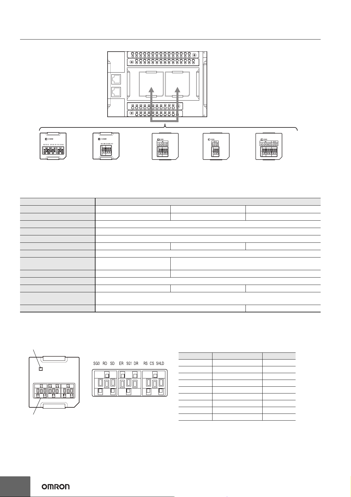
NX-series NX1P2 CPU Unit
Option Board
(NX1W-CIF01)
RS-232C
Option Board
(NX1W-CIF11/12)
RS-422A/485
Analog Input
Option Board
(NX1W-ADB21)
Analog Output
Option Board
(NX1W-DAB21V)
Analog I/O
Option Board
(NX1W-MAB221)
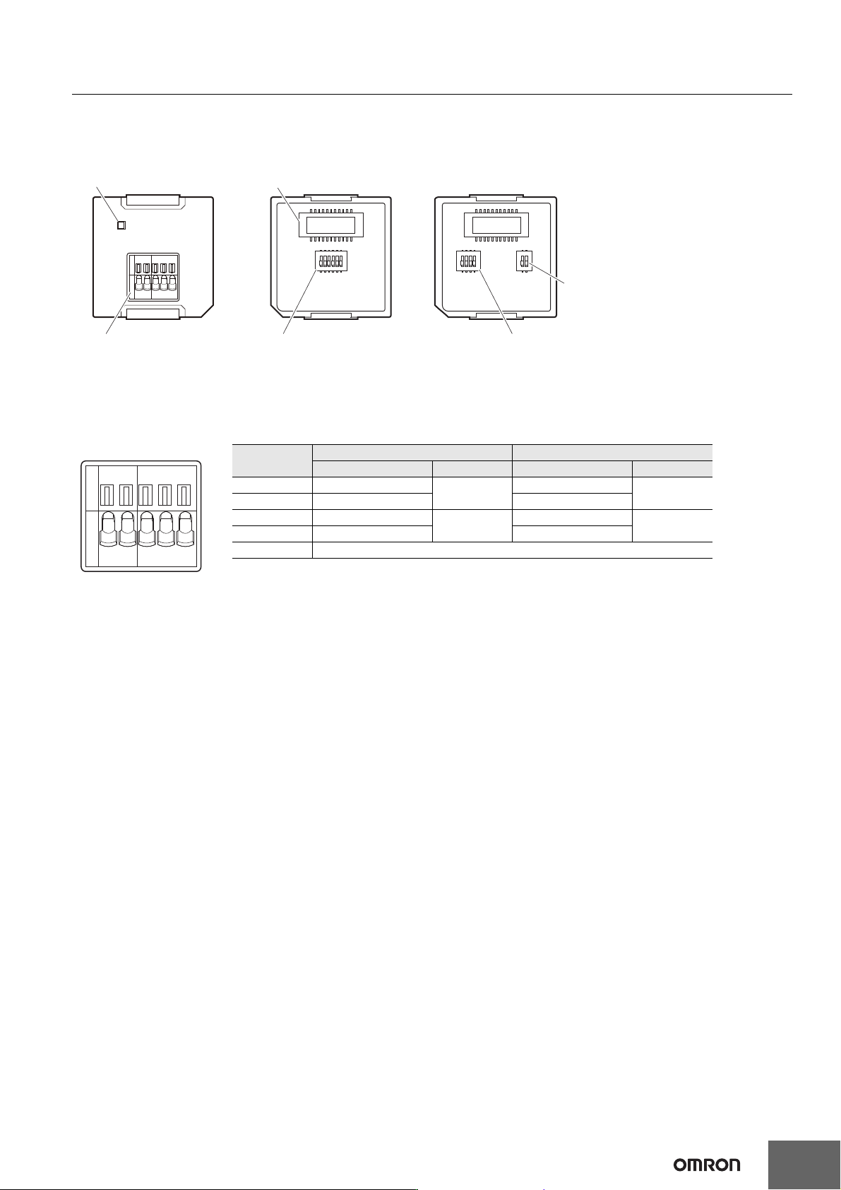
COMM
Communications status indicator
RS232C terminal block
SG0 RD SDER SG1 DR RS CS SHLD
RS-232C Terminal Block
Abbreviation Signal name I/O
SG0 Signal grounding ---
RD Receive data Input
SD Send data Output
ER Data terminal ready Output
SG1 Signal grounding ---
DR Data set ready Input
RS Send request Output
CS Data can be sent Input
SHLD Shield ---
Note: 1. As the Option Board does not have a 5 V power supply terminal, it cannot be connected to external
converters such as an CJ1W-CIF11 and NT-AL001, or an NV3W-M20L Programmable Terminal.
2. The terminal block is not removable.
Machine Automation Controller NX1P
31
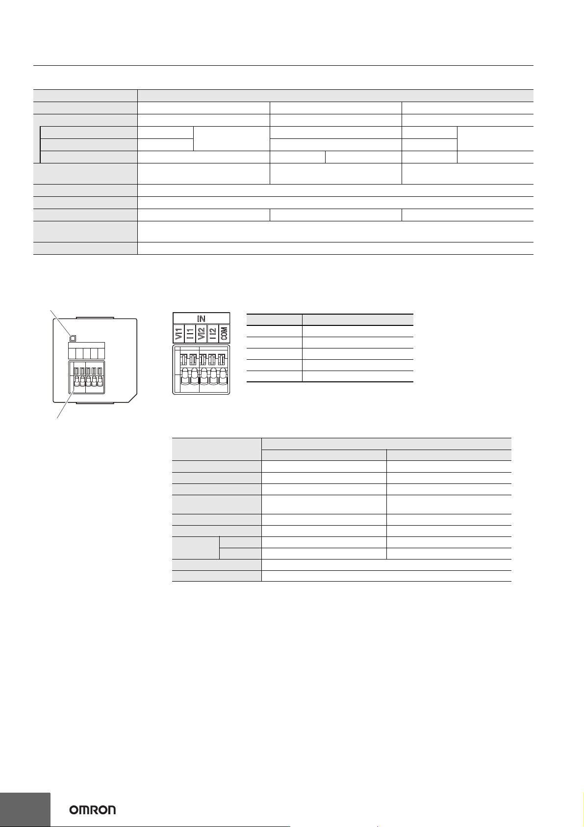
RS-422A/485 Option Board (NX1W-CIF11/NX1W-CIF12)
RS-422A/485 terminal
block
Operation setting DIP
switch (SW1)
Operation setting DIP
switch (SW1)
Operation setting DIP
switch (SW2)
Communications
status indicator
CPU Unit connector
Front Back (CIF11) Back (CIF12)
SW 1
1
2
3
4
5
6
O
N
1
2
3
4
O
N
1
2
O
N
SW 1 SW 2
COMM
RDA- RDB+ SDA- SDB+ SHLD
RS-422A/485 Terminal Block
RDA- RDB+ SDA- SDB+ SHLD
* For two-wire connection, either the RDA-/RDB+ pair or SDA-/SDB+ pair can be used.
Abbreviation
Four-wire type selected Two-wire type selected
Signal name I/O Signal name I/O
RDA- Reception data -
Input
Communication data -
I/O *
RDB+ Reception data + Communication data +
SDA- Transmission data -
Output
Communication data -
I/O *
SDB+ Transmission data + Communication data +
SHLD Shield
Note: All pins are turned OFF by default.
Use a narrow-tipped tool such as a flat-blade screwdriver to change the settings of the DIP switches.
Machine Automation Controller NX1P
32
Specifications of Analog I/O Option Board
* Projecting parts such as a terminal block is not included. When the Option Board is mounted to the CPU Unit, it protrudes through the CPU Unit
surface. Refer to the NX-series NX1P2 CPU Unit Hardware User’s Manual (Cat. No. W578) for details.
Analog Input Option Board (NX1W-ADB21)
Item Specification
Model NX1W-ADB21 NX1W-DAB21V NX1W-MAB221
I/O Analog input Analog output Analog I/O
Voltage input 0 to 10 V
2 words total
--- 0 to 10 V
2 words total
Current input 0 to 20 mA --- 0 to 20 mA
Voltage output --- 0 to 10 V 2 words 0 to 10 V 2 words
Connection type
Screwless clamping terminal block
(5 terminals)
Screwless clamping terminal block
(3 terminals)
Screwless clamping terminal block
(8 terminals)
Applicable wire size AWG24 to 20
Dimensions (mm) * 35.9 × 35.9 × 28.2 (W×H×D)
Weight 24 g 24 g 26 g
Power consumption
Included in the CPU Unit power consumption.
The Option Board power consumption is included in the definition of the CPU Unit power consumption.
Isolation method No isolation
ERR
IN
VI1
I I1
VI2
I I2
COM
A
nalog input terminal block
Status indicator
Analog Input Terminal Array
Note: When you use the current input, be sure to short-circuit V I1 with
I I1, and short-circuit V I2 with I I2.
Abbreviation Signal name
V I1 Voltage input 1
I I1 Current input 1
V I2 Voltage input 2
I I2 Current input 2
COM Input common
Analog Input Specifications
* Refer to the NX-series NX1P2 CPU Unit Built-in I/O and Option Board User’s Manual (Cat. No. W579)
for information on refresh time.
Item
Specification
Voltage input Current input
Input method Single-ended input Single-ended input
Input range 0 to 10 V 0 to 20 mA
Input conversion range 0 to 10.24 V 0 to 30 mA
Absolute maximum
rating
-1 to 15 V -4 to 30 mA
Input impedance 200 kΩ min. Approx. 250 Ω
Resolution 1/4,000 (full scale) 1/2,000 (full scale)
Overall
accuracy
25°C ±0.5% (full scale) ±0.6% (full scale)
0 to 55°C ±1.0% (full scale) ±1.2% (full scale)
Averaging processing Not provided
Conversion time Internal sampling time: 2 ms per point *