111.pdf - 第33页
Machine Automa tion Controller NX1P 33 Analog Output Option Board (NX1W-DAB21V) Analog I/O Option Board (NX1W-MAB221) ERR OUT VO1 VO2 COM Analog output terminal block Status indicator Analog Output Terminal Array Abbrevi…
Machine Automation Controller NX1P
32
Specifications of Analog I/O Option Board
* Projecting parts such as a terminal block is not included. When the Option Board is mounted to the CPU Unit, it protrudes through the CPU Unit
surface. Refer to the NX-series NX1P2 CPU Unit Hardware User’s Manual (Cat. No. W578) for details.
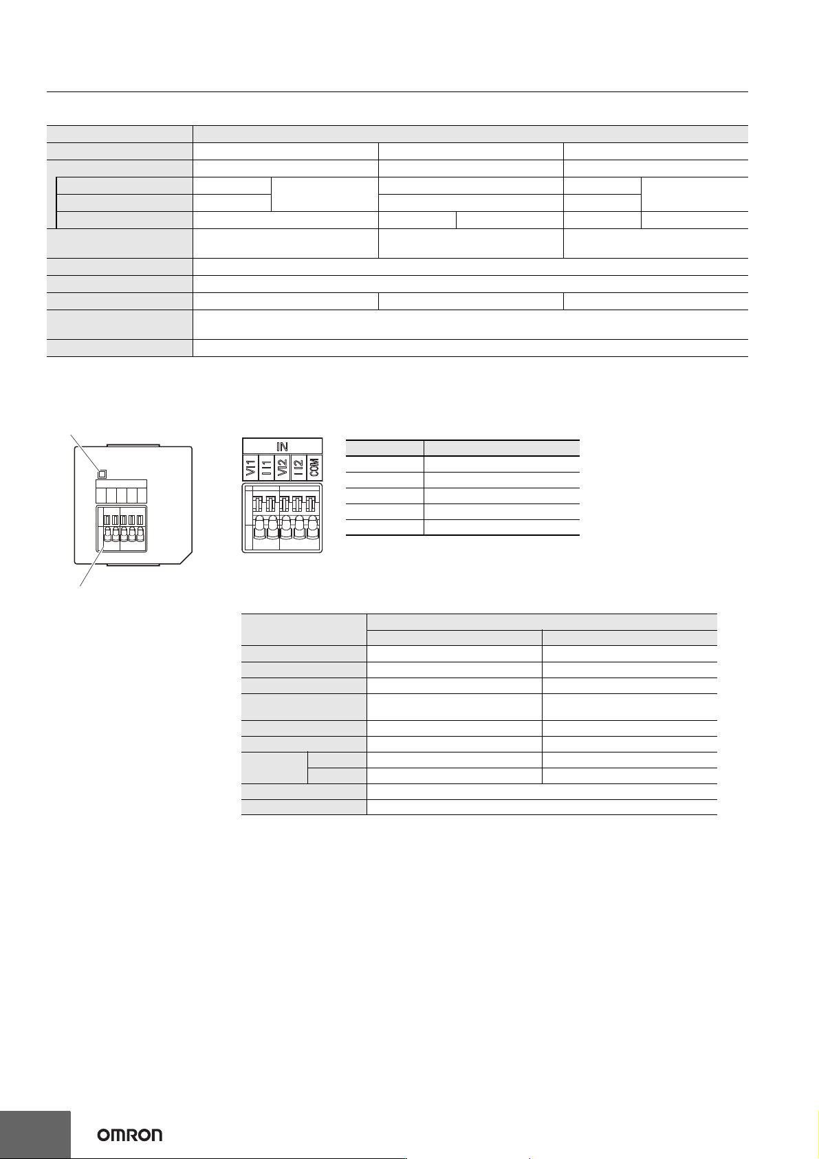
Analog Input Option Board (NX1W-ADB21)
Item Specification
Model NX1W-ADB21 NX1W-DAB21V NX1W-MAB221
I/O Analog input Analog output Analog I/O
Voltage input 0 to 10 V
2 words total
--- 0 to 10 V
2 words total
Current input 0 to 20 mA --- 0 to 20 mA
Voltage output --- 0 to 10 V 2 words 0 to 10 V 2 words
Connection type
Screwless clamping terminal block
(5 terminals)
Screwless clamping terminal block
(3 terminals)
Screwless clamping terminal block
(8 terminals)
Applicable wire size AWG24 to 20
Dimensions (mm) * 35.9 × 35.9 × 28.2 (W×H×D)
Weight 24 g 24 g 26 g
Power consumption
Included in the CPU Unit power consumption.
The Option Board power consumption is included in the definition of the CPU Unit power consumption.
Isolation method No isolation
ERR
IN
VI1
I I1
VI2
I I2
COM
A
nalog input terminal block
Status indicator
Analog Input Terminal Array
Note: When you use the current input, be sure to short-circuit V I1 with
I I1, and short-circuit V I2 with I I2.
Abbreviation Signal name
V I1 Voltage input 1
I I1 Current input 1
V I2 Voltage input 2
I I2 Current input 2
COM Input common
Analog Input Specifications
* Refer to the NX-series NX1P2 CPU Unit Built-in I/O and Option Board User’s Manual (Cat. No. W579)
for information on refresh time.
Item
Specification
Voltage input Current input
Input method Single-ended input Single-ended input
Input range 0 to 10 V 0 to 20 mA
Input conversion range 0 to 10.24 V 0 to 30 mA
Absolute maximum
rating
-1 to 15 V -4 to 30 mA
Input impedance 200 kΩ min. Approx. 250 Ω
Resolution 1/4,000 (full scale) 1/2,000 (full scale)
Overall
accuracy
25°C ±0.5% (full scale) ±0.6% (full scale)
0 to 55°C ±1.0% (full scale) ±1.2% (full scale)
Averaging processing Not provided
Conversion time Internal sampling time: 2 ms per point *
Machine Automation Controller NX1P
33
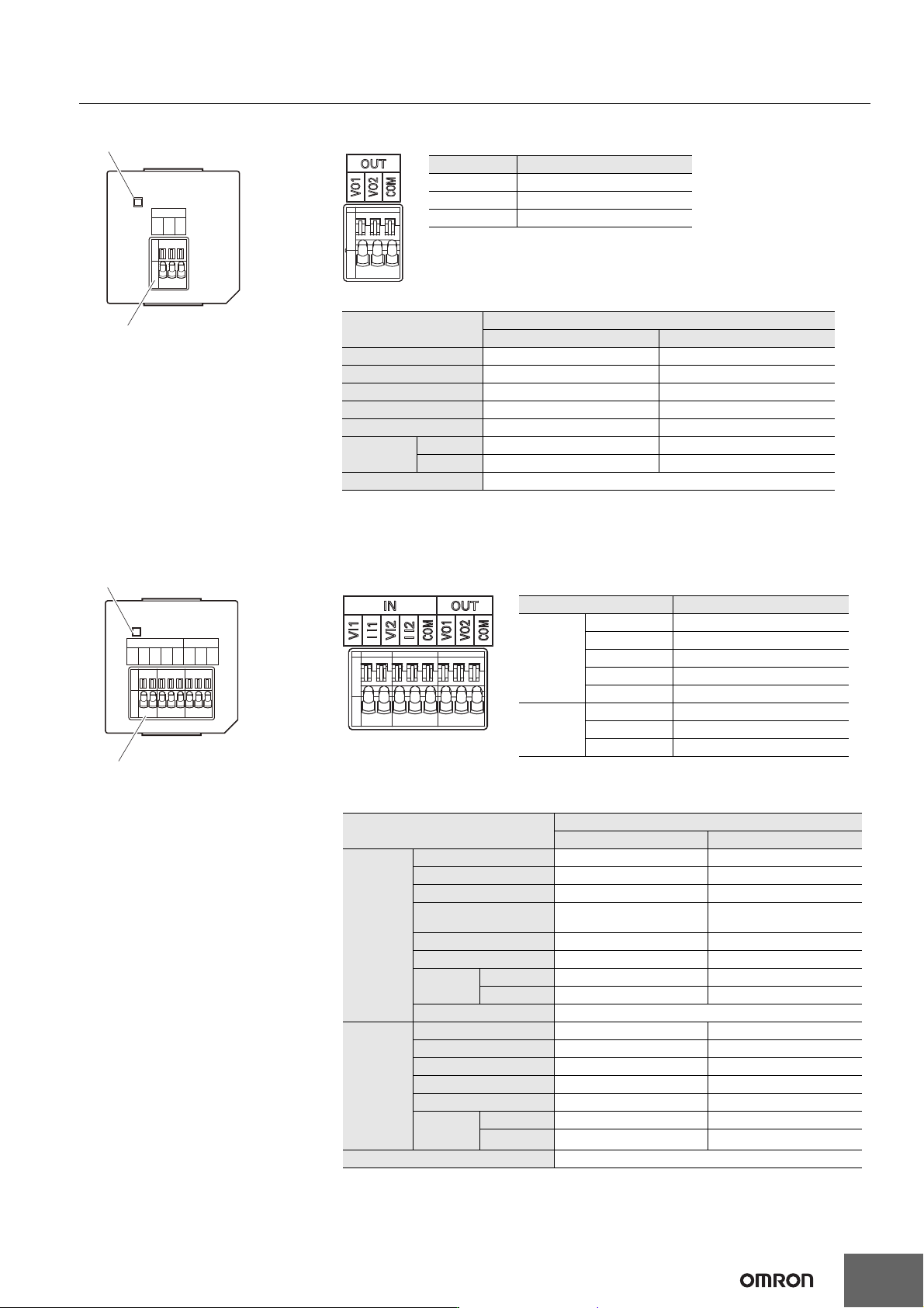
Analog Output Option Board (NX1W-DAB21V)
Analog I/O Option Board (NX1W-MAB221)
ERR
OUT
VO1
VO2
COM
Analog output terminal block
Status indicator
Analog Output Terminal Array
Abbreviation Signal name
VO1 Voltage output 1
VO2 Voltage output 1
COM Output common
Analog Output Specifications
* Refer to the NX-series NX1P2 CPU Unit Built-in I/O and Option Board User’s Manual (Cat. No.
W579) for information on refresh time.
Item
Specification
Voltage output Current output
Output range 0 to 10 V ---
Output conversion range 0 to 10.24 V ---
Allowable load resistance 2 kΩ min. ---
Output impedance 0.5 Ω max. ---
Resolution 1/4,000 (full scale: 4,000) ---
Overall
accuracy
25°C ±0.5% (full scale) ---
0 to 55°C ±1.0% (full scale) ---
Conversion time Internal sampling time: 2 ms per point *
ERR
OUT
VO1
VO2
COM
IN
VI1
I I1
VI2
I I2
COM
Analog output terminal block
Status indicator
Analog I/O Terminal Array
Note: When you use the current input, be sure to short-circuit VI1
with II1, and short-circuit VI2 with II2.
Abbreviation Signal name
IN
VI1 Voltage input 1
II1 Current input 1
VI2 Voltage input 2
II2 Current input 2
COM Input common
OUT
VO1 Voltage output 1
VO2 Voltage output 2
COM Output common
Analog I/O Specifications
* Refer to the NX-series NX1P2 CPU Unit Built-in I/O and Option Board User’s Manual (Cat. No.
W579) for information on refresh time.
Item
Specification
Voltage I/O Current I/O
Analog
input
section
Input method Single-ended input Single-ended input
Input range 0 to 10 V 0 to 20 mA
Input conversion range 0 to 10.24 V 0 to 30 mA
Absolute maximum
rating
-1 to 15 V -4 to 30 mA
Input impedance 200 kΩ min. Approx. 250 Ω
Resolution 1/4,000 (full scale) 1/2,000 (full scale)
Overall
accuracy
25°C ±0.5% (full scale) ±0.6% (full scale)
0 to 55°C ±1.0% (full scale) ±1.2% (full scale)
Averaging processing Not provided
Analog
output
section
Output range 0 to 10 V ---
Output conversion range 0 to 10.24 V ---
Allowable load resistance 2 kΩ min. ---
Output impedance 0.5 Ω max. ---
Resolution 1/4,000 (full scale) ---
Overall
accuracy
25°C ±0.5% (full scale) ---
0 to 55°C ±1.0% (full scale)
---
Conversion time Internal conversion time: 6 ms (Total of 4 channels) *
Machine Automation Controller NX1P
34
NX Unit Configuration
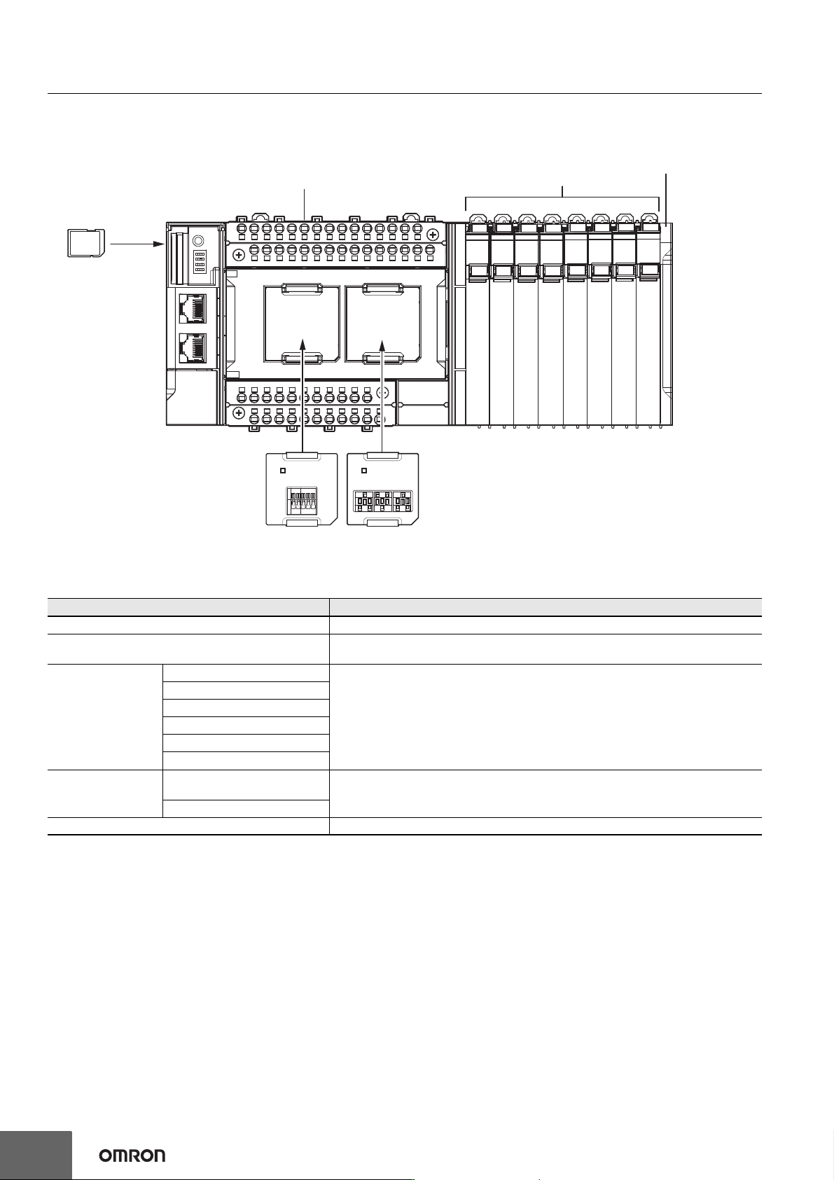
CPU Rack
The CPU Rack consists of an NX-series NX1P2 CPU Unit, NX Units, and an End Cover.
Up to eight NX Units can be connected.
Configuration Remarks
NX-series NX1P2 CPU Unit One required for every CPU Rack.
End Cover
Must be connected to the right end of the CPU Rack. One End Cover is provided with
the CPU Unit.
NX Unit
Digital I/O Unit • Up to eight Units (including System Units such as Additional I/O Power Supply Unit)
can be mounted to each Expansion Rack.
• For the NX Units connectable to the CPU Unit, refer to the Ordering Information
page.
• You cannot mount NX-series Safety Control Units on the CPU Unit and use them.
Use NX-series Safety Control Units as a subsystem on EtherCAT.
• Refer to the NX-series Data Reference Manual (Cat. No. W525. Revision 11 or later)
for information such as restrictions on the NX Units.
Analog I/O Unit
System Unit
Position Interface Unit
Communication Interface Unit
Load Cell Input Unit
Option Board
Serial Communications Option
Board
One or two Option Boards can be connected to the CPU Unit.
Analog I/O Option Board
SD Memory Card Install as required.
NX-series NX1P2 CPU Unit
Option Board
(1 or 2)
SD Memory
Card
End CoverNX Units
(8 Units max.)