111.pdf - 第34页
Machine Automati on Controller NX1P 34 NX Unit Configuration CPU Rack The CPU Rack consists of an NX-s eries NX1P2 CPU Unit, NX Units, and an End Cover. Up to eight NX Units can be connected. Configuration Remarks NX-ser…
Machine Automation Controller NX1P
33
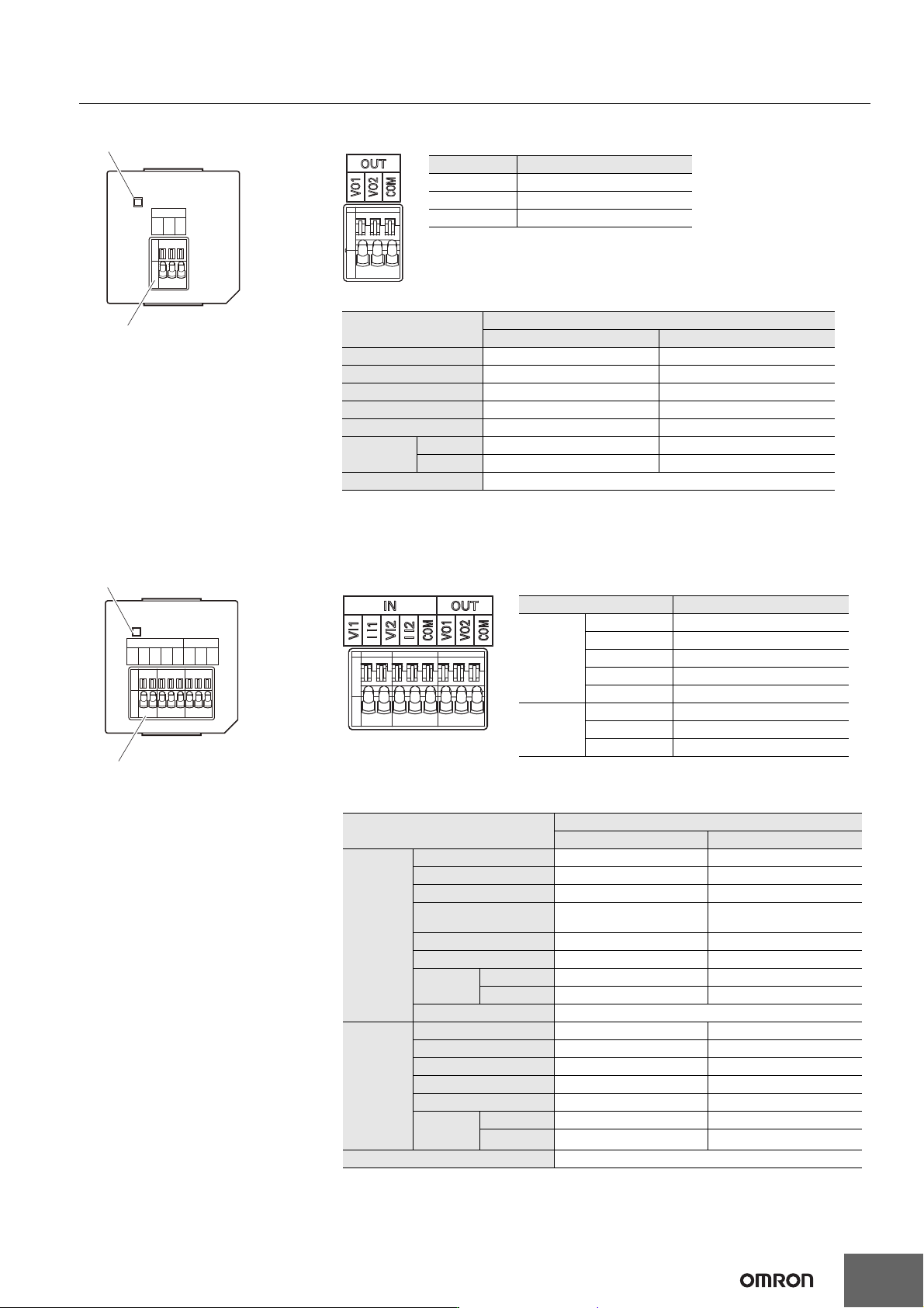
Analog Output Option Board (NX1W-DAB21V)
Analog I/O Option Board (NX1W-MAB221)
ERR
OUT
VO1
VO2
COM
Analog output terminal block
Status indicator
Analog Output Terminal Array
Abbreviation Signal name
VO1 Voltage output 1
VO2 Voltage output 1
COM Output common
Analog Output Specifications
* Refer to the NX-series NX1P2 CPU Unit Built-in I/O and Option Board User’s Manual (Cat. No.
W579) for information on refresh time.
Item
Specification
Voltage output Current output
Output range 0 to 10 V ---
Output conversion range 0 to 10.24 V ---
Allowable load resistance 2 kΩ min. ---
Output impedance 0.5 Ω max. ---
Resolution 1/4,000 (full scale: 4,000) ---
Overall
accuracy
25°C ±0.5% (full scale) ---
0 to 55°C ±1.0% (full scale) ---
Conversion time Internal sampling time: 2 ms per point *
ERR
OUT
VO1
VO2
COM
IN
VI1
I I1
VI2
I I2
COM
Analog output terminal block
Status indicator
Analog I/O Terminal Array
Note: When you use the current input, be sure to short-circuit VI1
with II1, and short-circuit VI2 with II2.
Abbreviation Signal name
IN
VI1 Voltage input 1
II1 Current input 1
VI2 Voltage input 2
II2 Current input 2
COM Input common
OUT
VO1 Voltage output 1
VO2 Voltage output 2
COM Output common
Analog I/O Specifications
* Refer to the NX-series NX1P2 CPU Unit Built-in I/O and Option Board User’s Manual (Cat. No.
W579) for information on refresh time.
Item
Specification
Voltage I/O Current I/O
Analog
input
section
Input method Single-ended input Single-ended input
Input range 0 to 10 V 0 to 20 mA
Input conversion range 0 to 10.24 V 0 to 30 mA
Absolute maximum
rating
-1 to 15 V -4 to 30 mA
Input impedance 200 kΩ min. Approx. 250 Ω
Resolution 1/4,000 (full scale) 1/2,000 (full scale)
Overall
accuracy
25°C ±0.5% (full scale) ±0.6% (full scale)
0 to 55°C ±1.0% (full scale) ±1.2% (full scale)
Averaging processing Not provided
Analog
output
section
Output range 0 to 10 V ---
Output conversion range 0 to 10.24 V ---
Allowable load resistance 2 kΩ min. ---
Output impedance 0.5 Ω max. ---
Resolution 1/4,000 (full scale) ---
Overall
accuracy
25°C ±0.5% (full scale) ---
0 to 55°C ±1.0% (full scale)
---
Conversion time Internal conversion time: 6 ms (Total of 4 channels) *
Machine Automation Controller NX1P
34
NX Unit Configuration
CPU Rack
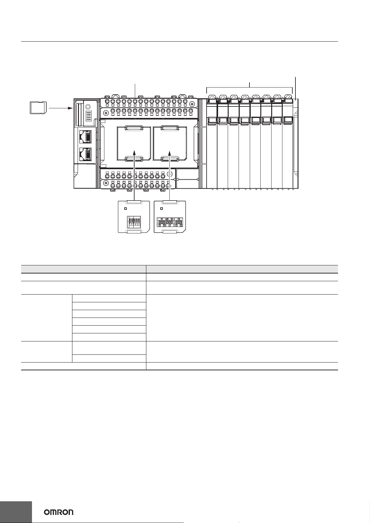
The CPU Rack consists of an NX-series NX1P2 CPU Unit, NX Units, and an End Cover.
Up to eight NX Units can be connected.
Configuration Remarks
NX-series NX1P2 CPU Unit One required for every CPU Rack.
End Cover
Must be connected to the right end of the CPU Rack. One End Cover is provided with
the CPU Unit.
NX Unit
Digital I/O Unit • Up to eight Units (including System Units such as Additional I/O Power Supply Unit)
can be mounted to each Expansion Rack.
• For the NX Units connectable to the CPU Unit, refer to the Ordering Information
page.
• You cannot mount NX-series Safety Control Units on the CPU Unit and use them.
Use NX-series Safety Control Units as a subsystem on EtherCAT.
• Refer to the NX-series Data Reference Manual (Cat. No. W525. Revision 11 or later)
for information such as restrictions on the NX Units.
Analog I/O Unit
System Unit
Position Interface Unit
Communication Interface Unit
Load Cell Input Unit
Option Board
Serial Communications Option
Board
One or two Option Boards can be connected to the CPU Unit.
Analog I/O Option Board
SD Memory Card Install as required.
NX-series NX1P2 CPU Unit
Option Board
(1 or 2)
SD Memory
Card
End CoverNX Units
(8 Units max.)
Machine Automation Controller NX1P
35
Battery
The battery is not mounted when the product is shipped.
To turn OFF the power supply to the equipment for a certain period of time by using the clock data for programming, event logs, etc., you need a
separately-sold battery to retain the clock data.
The following describes the purpose of the battery mounting, the battery model, and the battery-related error detection and clock data settings.
Purpose of the Battery Mounting
The battery is used to retain the clock data while the power is not supplied to the CPU Unit. The clock data is retained by the built-in capacitor
whether the battery is mounted or not, but the retention period depends on the continuous power-ON time of the CPU Unit, as shown below.
* This is equivalent to the time to charge a built-in capacitor in which no electric charge is accumulated.
When you use the clock data for programming, use a battery if you cannot ensure the continuous power-ON time shown above or the power-OFF
time is longer than the above power-ON time.
The following data (other than the clock data) is retained in the built-in non-volatile memory, so they are not lost even if the battery and built-in
capacitor are fully discharged.
• User program
• Set values
• Variables retained during power interruption
• Event logs
Battery Model
The table below shows the model and specifications of the battery that can be used.
Continuous power-ON time of CPU Unit *
Retention period during no power supply at
an ambient temperature of 40°C
100 hours Approx. 10 days
8 hours Approx. 8 days
1 hour Approx. 7 days
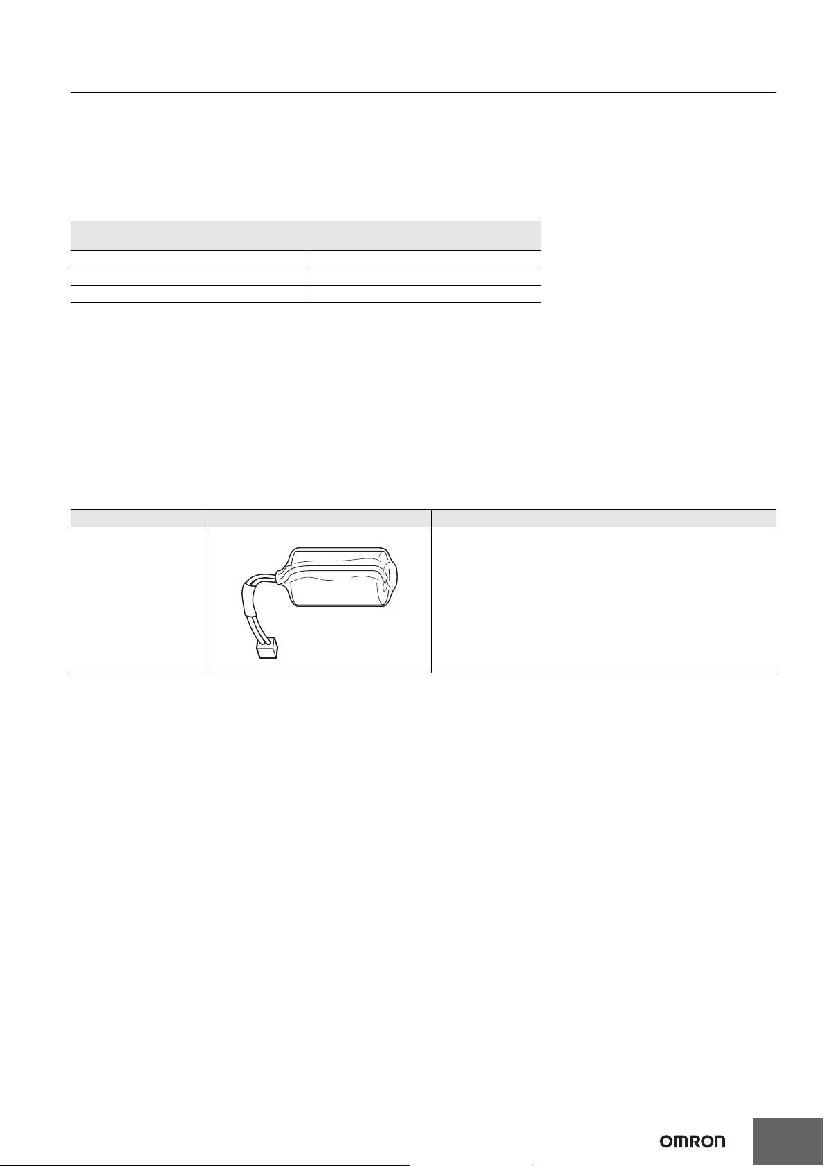
Model Appearance Specification
CJ1W-BAT01
Service life: 5 years
Refer to the NX-series NX1P2 CPU Unit Hardware User’s Manual
(Cat. No. W578) for details.
The clock information is retained during power interruptions.