111.pdf - 第26页
Machine Automati on Controller NX1P 26 Input Specifications The specifications depends on t he input terminal numbers of the model. *1 *1. The following specifications apply to models with lot number 18 321M (products pr…
Machine Automation Controller NX1P
25
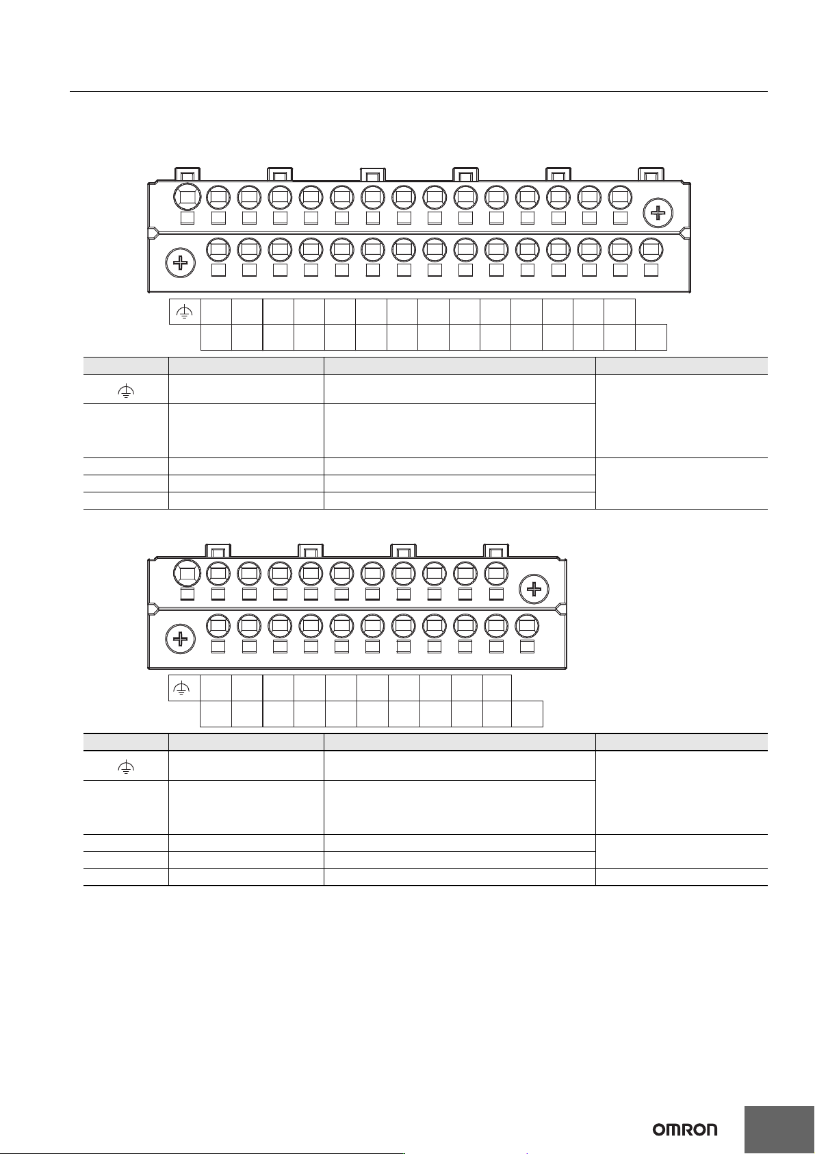
Input Terminal Block
Terminal Arrangement
The description is given for each CPU Unit model.
NX1P2-140DT
NX1P2-9024DT
Symbol Terminal name Description Reference
Functional ground terminal
The functional ground terminal. Connect the ground
wire to the terminal.
Refer to the NX-series NX1P2
CPU Unit Hardware User’s
Manual (Cat. No. W578) for
details.
+/- Unit power supply terminals
These terminals are connected to the Unit power
supply.
The + terminals and - terminals are internally
connected to each other.
COM Common terminal Common terminal for the input circuits
Refer to the Input Specifications
page.
00 to 15 Input terminals General-purpose input A
16 to 23 Input terminals General-purpose input B
Symbol Terminal name Description Reference
Functional ground terminal
The functional ground terminal. Connect the ground
wire to the terminal.
Refer to the NX-series NX1P2
CPU Unit Hardware User’s
Manual (Cat. No. W578) for
details.
+/- Unit power supply terminals
These terminals are connected to the Unit power
supply.
The + terminals and - terminals are internally
connected to each other.
COM Common terminal Common terminal for the input circuits
Refer to the Input Specifications
page.
00 to 13 Input terminals General-purpose input A
NC NC Do not connect anything. ---
+-
-+
COM
00
17
18
15
16
13
14
11
12
09
10
07
08
05
06
03
04
01
02
19
20
21
22 23
NC
13
NC
11
12
09
10
07
08
05
06
03
04
01
02
COM
00
-
-
+
+
Machine Automation Controller NX1P
26
Input Specifications
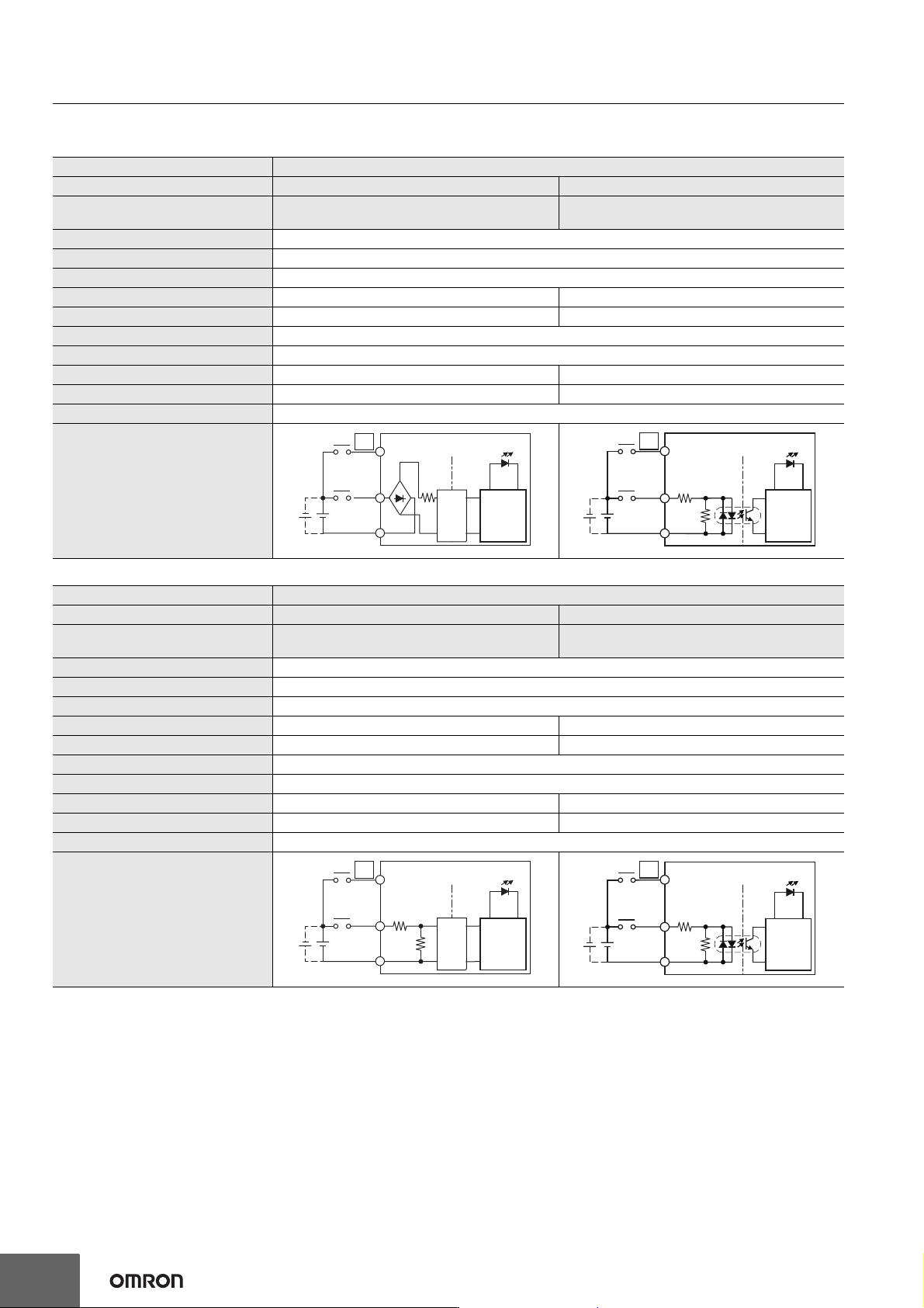
The specifications depends on the input terminal numbers of the model. *1
*1. The following specifications apply to models with lot number 18321M (products produced in March 2021) or earlier.
*2. These values are the fixed response time needed by the hardware. A value from 0 to 32 ms (default: 1 ms) that is set on the Support Software
is added to these values.
*3. Set the filter time for every 4 points.
Item Specification
Input type General-purpose input A General-purpose input B
Input terminal number
NX1P2-140DT: 00 to 15
NX1P2-9024DT: 00 to 13
NX1P2-140DT: 16 to 23
NX1P2-9024DT: None
Internal I/O common For both NPN/PNP
Input voltage 24 VDC (15 to 28.8 VDC)
Connected sensor Two-wire or three-wire sensors
Input impedance −−− 4.3 kΩ
Input current 4.22 mA 5.3 mA typical
ON voltage 15 VDC min.
OFF voltage/current 5 VDC max./1 mA max.
ON response time *2 2.5 µs max. 1 ms max.
OFF response time *2 2.5 µs max. 1 ms max.
ON/OFF filter time *3 No filter, 0.25 ms, 0.5 ms, 1 ms (default), 2 ms, 4 ms, 8 ms, 16 ms, 32 ms, 64 ms, 128 ms, 256 ms
Circuit configuration
Item Specification
Input type General-purpose input A General-purpose input B
Input terminal number
NX1P2-140DT: 00 to 15
NX1P2-9024DT: 00 to 13
NX1P2-140DT: 16 to 23
NX1P2-9024DT: None
Internal I/O common For both NPN/PNP
Input voltage 24 VDC (15 to 28.8 VDC)
Connected sensor Two-wire or three-wire sensors
Input impedance 4.0 kΩ 4.3 kΩ
Input current 5.8 mA typical 5.3 mA typical
ON voltage 15 VDC min.
OFF voltage/current 5 VDC max./1 mA max.
ON response time *2 2.5 µs max. 1 ms max.
OFF response time *2 2.5 µs max. 1 ms max.
ON/OFF filter time *3 No filter, 0.25 ms, 0.5 ms, 1 ms (default), 2 ms, 4 ms, 8 ms, 16 ms, 32 ms, 64 ms, 128 ms, 256 ms
Circuit configuration
Input indicator
Isola-
tion
circuits
Internal
circuits
COM
00
15(13)
. . .
. . .
IN
23
16
IN
910 Ω
4.3 kΩ
Input indicator
Internal
circuits
COM
. . .
. . .
. . .
. . .
IN
Input indicator
Isola-
tion
circuits
Internal
circuits
COM
00
4.0 kΩ
1.1 kΩ
15 (13)
23
16
IN
910 Ω
4.3 kΩ
Input indicator
Internal
circuits
COM
. . .
. . .
Machine Automation Controller NX1P
27
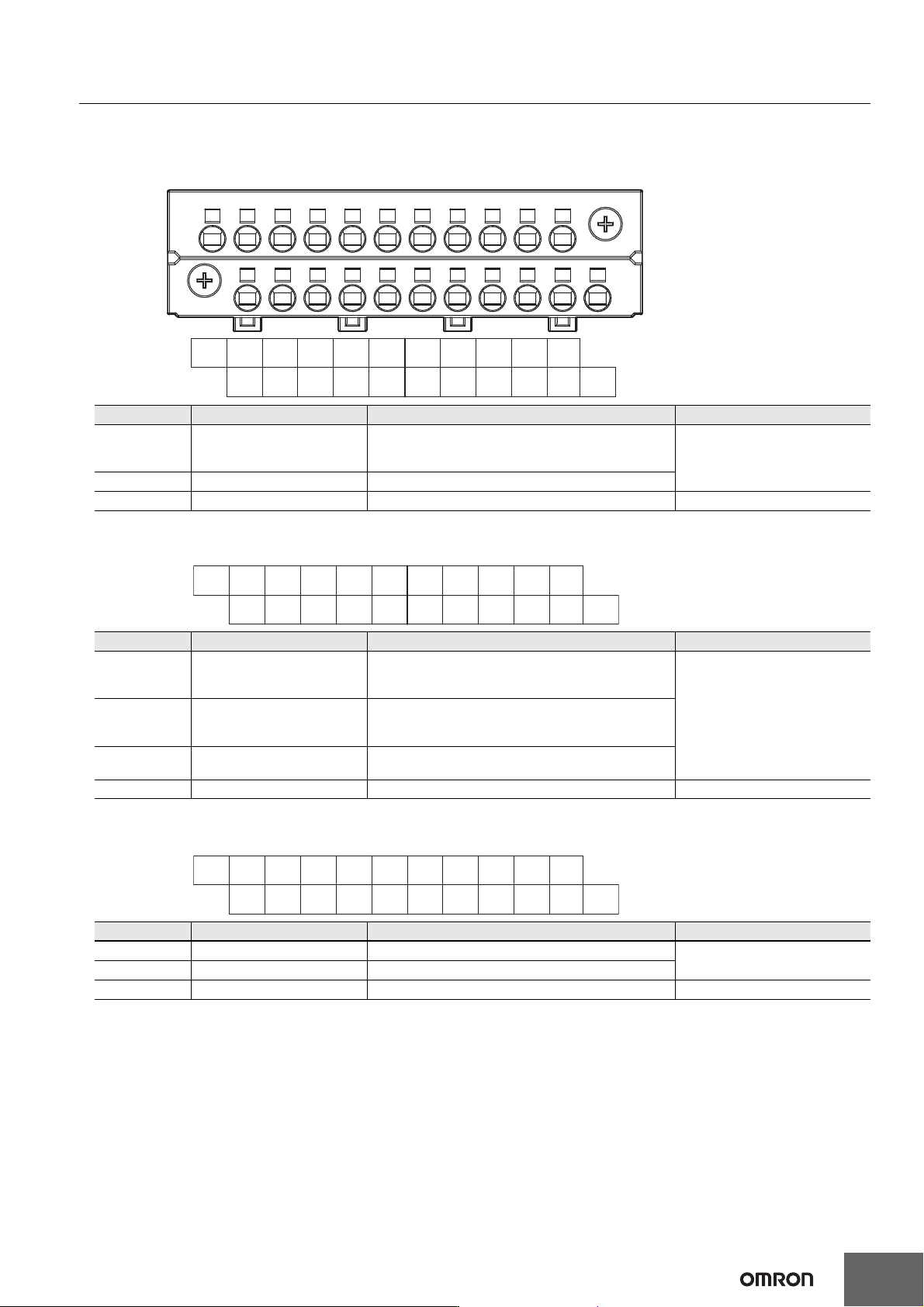
Output Terminal Block
Terminal Arrangement
The description is given for each CPU Unit model.
NX1P2-140DT
NX1P2-140DT1
The appearance of the terminal block is the same as NX1P2-140DT.
NX1P2-9024DT
The appearance of the terminal block is the same as NX1P2-140DT.
Symbol Terminal name Description Reference
C0 (0V),
C1 (0V)
Common terminal
Connected to the 0-V side of the I/O power supply.
C0 (0V) and C1 (0V) are independent from each other
inside the CPU Unit.
Refer to the Output Specifications
page.
00 to 15 Output terminals NPN (sinking) type output
NC NC Do not connect anything. ---
Symbol Terminal name Description Reference
C0 (+V),
C1 (+V)
Common terminal
Connected to the 24-V side of the I/O power supply.
C0 (+V) and C1 (+V) are independent from each other
inside the CPU Unit.
Refer to the Output Specifications
page.
0V0, 0V1 0 V terminal
Supplies 0 V for the internal circuits for driving.
0V0 and 0V1 are independent from each other inside
the CPU Unit.
00 to 15 Output terminals
PNP (sourcing) type output with the load short-circuit
protection function
NC NC Do not connect anything. ---
Symbol Terminal name Description Reference
C0 (0V) Common terminal Connected to the 0-V side of the I/O power supply.
Refer to the Output Specifications
page.
00 to 09 Output terminals NPN (sinking) type output
NC NC Do not connect anything. ---
NC
14
15
12
13
10
11
08
09
NC
C1
(0V)
06
07
04
05
02
03
00
01
NCNC
C0
(0V)
NC
14
15
12
13
10
11
08
09
C1
(+V)
0V1
06
07
04
05
02
03
00
01
C0
(+V)
NC
0V0
NC
NC
NC
NC
NC
NC
NC
NC08
NC09
06
07
04
05
02
03
00
01
C0
(0V)
NC NC