111.pdf - 第23页
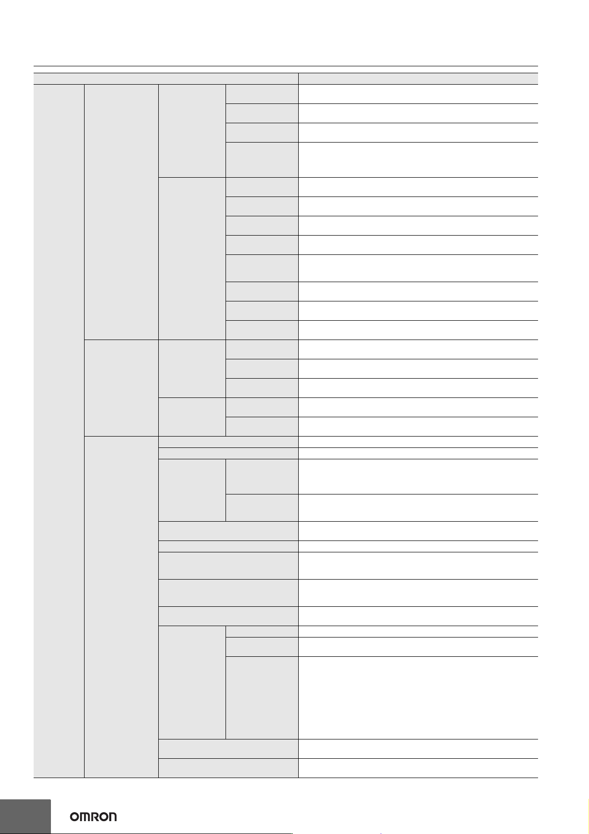
Machine Automa tion Controller NX1P 23 Motion Control External Interface Signals The Servo Drive input signals l isted on t he right ar e used. Home signal, home proximity signal, positive limit signal, nega tive limit s…
Machine Automation Controller NX1P
22
Motion
Control
Axes Groups
Multi-axes
Coordinated
Control
Absolute Linear
Interpolation
Linear interpolation is performed to a specified absolute position.
Relative Linear
Interpolation
Linear interpolation is performed to a specified relative position.
Circular 2D
Interpolation
Circular interpolation is performed for two axes.
Axes Group Cyclic
Synchronous
Absolute
Positioning
A positioning command is output each control period in Position Control
Mode.
Auxiliary
Functions for
Multi-axes
Coordinated
Control
Resetting Axes
Group Errors
Axes group errors and axis errors are cleared.
Enabling Axes
Groups
Motion of an axes group is enabled.
Disabling Axes
Groups
Motion of an axes group is disabled.
Stopping Axes
Groups
All axes in interpolated motion are decelerated to a stop.
Immediately
Stopping Axes
Groups
All axes in interpolated motion are stopped immediately.
Setting Axes Group
Override Factors
The blended target velocity is changed during interpolated motion.
Reading Axes
Group Positions
The command current positions and actual current positions of an axes group
can be read.
Changing the Axes
in an Axes Group
The Composition Axes parameter in the axes group parameters can be
overwritten temporarily.
Common Items
Cams
Setting Cam Table
Properties
The end point index of the cam table that is specified in the input parameter
is changed.
Saving Cam Tables
The cam table that is specified with the input parameter is saved in non-
volatile memory in the CPU Unit.
Generating Cam
Tables
The cam table is generated from the cam property and cam node that is
specified in input parameters.
Parameters
Writing MC Settings
Some of the axis parameters or axes group parameters are overwritten
temporarily.
Changing Axis
Parameters
You can access and change the axis parameters from the user program.
Auxiliary Functions
Count Modes
You can select either Linear Mode (finite length) or Rotary Mode (infinite length).
Unit Conversions You can set the display unit for each axis according to the machine.
Acceleration/
Deceleration
Control
Automatic
Acceleration/
Deceleration
Control
Jerk is set for the acceleration/deceleration curve for an axis motion or axes
group motion.
Changing the
Acceleration and
Deceleration Rates
You can change the acceleration or deceleration rate even during
acceleration or deceleration.
In-Position Check
You can set an in-position range and in-position check time to confirm when
positioning is completed.
Stop Method
You can set the stop method to the immediate stop input signal or limit input signal.
Re-execution of Motion Control
Instructions
You can change the input variables for a motion control instruction during
execution and execute the instruction again to change the target values
during operation.
Multi-execution of Motion Control
Instructions (Buffer Mode)
You can specify when to start execution and how to connect the velocities
between operations when another motion control instruction is executed
during operation.
Continuous Axes Group Motions
(Transition Mode)
You can specify the Transition Mode for multi-execution of instructions for
axes group operation.
Monitoring
Functions
Software limits The movement range of an axis is monitored.
Following Error
The error between the command current value and the actual current value is
monitored for each axis.
Velocity,
Acceleration Rate,
Deceleration Rate,
Torque,
Interpolation
Velocity,
Interpolation
Acceleration Rate,
and Interpolation
Dceleration Rate
You can set and monitor warning values for each axis and each axes group.
Absolute Encoder Support
You can use an OMRON 1S-series Servomotor or G5-series Servomotor with
an Absolute Encoder to eliminate the need to perform homing at startup.
Input Signal Logic Inversion
You can inverse the logic of immediate stop input signal, positive limit input
signal, negative limit input signal, or home proximity input signal.
Item NX1P2
Machine Automation Controller NX1P
23
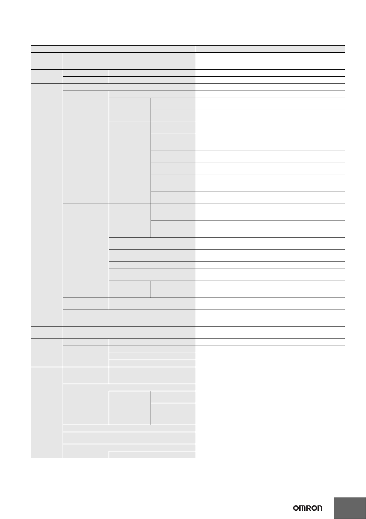
Motion
Control
External Interface Signals
The Servo Drive input signals listed on the right are used.
Home signal, home proximity signal, positive limit signal, negative limit signal,
immediate stop signal, and interrupt input signal
Unit (I/O)
Management
EtherCAT slaves Maximum Number of Slaves 16
CJ-Series Units Maximum Number of Units Not supported
Communications
Peripheral USB Port Not supported
Built-in EtherNet/IP
Port
Communications Protocol TCP/IP and UDP/IP
CIP
Communications
Service
Tag Dta Links
Programless cyclic data exchange is performed with the devices on the
EtherNet/IP network.
Message
Communications
CIP commands are sent to or received from the devices on the EtherNet/IP
network.
TCP/IP
Applications
Socket Services
Data is sent to and received from any node on Ethernet using the UDP or TCP
protocol. Socket communications instructions are used.
Secure Socket
service (Client)
Establishes a TLS session with the TCP protocol, and sends and receives
arbitrary data to and from the server and any node on the Ethernet using
instructions for secure socket communication.
FTP Client
Files are transferred via FTP from the CPU Unit to computers or Controllers
at other Ethernet nodes. FTP client communications instructions are used.
FTP Server
Files can be read from or written to the SD Memory Card in the CPU Unit from
computers at other Ethernet nodes.
Automatic Clock
Adjustment
Clock information is read from the NTP server at the specified time or at a
specified interval after the power supply to the CPU Unit is turned ON. The
internal clock time in the CPU Unit is updated with the read time.
SNMP Agent
Built-in EtherNet/IP port internal status information is provided to network
management software that uses an SNMP manager.
EtherCAT Port
Supported
Services
Process Data
Communications
A communications method to exchange control information in cyclic
communications between the EtherCAT master and slaves.
This communications method is defined by CoE.
SDO
Communications
A communications method to exchange control information in noncyclic event
communications between EtherCAT master and slaves.
This communications method is defined by CoE.
Network Scanning
Information is read from connected slave devices and the slave configuration
is automatically generated.
DC (Distributed Clock)
Time is synchronized by sharing the EtherCAT system time among all
EtherCAT devices (including the master).
Enable/Disable Settings for Slaves The slaves can be enabled or disabled as communications targets.
Disconnecting/Connecting Slaves
Temporarily disconnects a slave from the EtherCAT network for maintenance,
such as for replacement of the slave, and then connects the slave again.
Supported
Application
Protocol
CoE SDO messages of the CAN application can be sent to slaves via EtherCAT
Serial
Communication
Protocol
Host link (FINS), no-protocol, and Modbus-RTU master (when connected to
the Serial Communications Option Board)
Communications Instructions
FTP client instructions, CIP communications instructions, socket
communications instructions, SDO message instructions, noprotocol
communications instructions, and Modbus RTU protocol instructions
Operation
Management
RUN Output Contacts Not supported
System
Management
Event Logs Function Events are recorded in the logs
Maximum Number of
Events
System Event Log 576 *2
Access Event Log 528 *3
User-defined Event Log 512
Debugging
Online Editing Single
Programs, function blocks, functions, and global variables can be changed
online.
More than one operators can change POUs individually via network.
Forced Refreshing The user can force specific variables to TRUE or FALSE.
Maximum Number
of Forced
Variables
Device Variables for
EtherCAT Slaves
64
Device Variables for
CJ-series Units and
Variables with AT
Specifications
Not supported
MC Test Run Motor operation and wiring can be checked from the Sysmac Studio.
Synchronizing
The project file in the Sysmac Studio and the data in the CPU Unit can be
made the same when online.
Differentiation Monitoring You can monitor when a variable changes to TRUE or changes to FALSE.
Maximum Number of Contacts 8
Item NX1P2
Machine Automation Controller NX1P
24
*1. Inline ST is supported. (Inline ST is ST that is written as an element in a ladder diagram.)
*2. This is the total of 512 events for the CPU Unit and 64 events for the NX Unit.
*3. This is the total of 512 events for the CPU Unit and 16 events for the NX Unit.
*4. Restore is supported with unit version 1.14 or later.
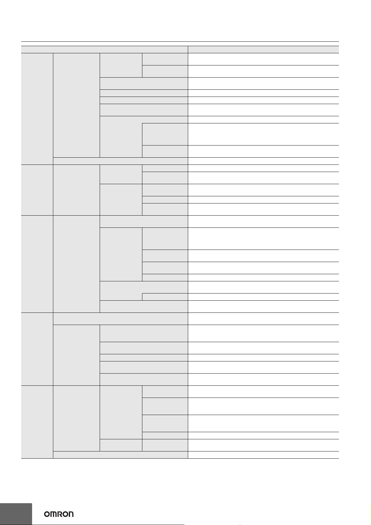
Debugging
Data Tracing
Types
Single Triggered
Trace
When the trigger condition is met, the specified number of samples are taken
and then tracing stops automatically.
Continuous Trace
Data tracing is executed continuously and the trace data is collected by the
Sysmac Studio.
Maximum Number of Simultaneous Data
Traces
2
Maximum Number of Records 10000
Maximum Number of Sampled Variables 48 variables
Timing of Sampling
Sampling is performed for the specified task period, at the specified time, or
when a sampling instruction is executed.
Triggered Traces Trigger conditions are set to record data before and after an event.
Trigger Conditions
When BOOL variable changes to TRUE or FALSE
Comparison of non-BOOL variable with a constant
Comparison Method: Equals (=), Greater than (>), Greater than or
equals (≥), Less Than (<), Less than or equals (≤), Not equal (≠)
Delay
Trigger position setting: A slider is used to set the percentage of sampling
before and after the trigger condition is met.
Simulation The operation of the CPU Unit is emulated in the Sysmac Studio.
Reliability
functions
Self-Diagnosis
Controller Errors
Levels Major faults, partial faults, minor faults, observation, and information
Maximum number of
message languages
9 (Sysmac Studio)
2 (NS-series PT)
User-defined
Errors
Function
User-defined errors are registered in advance and then records are created
by executing instructions.
Levels 8
Maximum number of
message languages
9
Security
Protecting Software
Assets and
Preventing
Operating Mistakes
CPU Unit Names and Serial IDs
When going online to a CPU Unit from the Sysmac Studio, the CPU Unit name
in the project is compared to the name of the CPU Unit being connected to.
Protection
User Program
Transfer with no
Restoration
Information
You can prevent reading data in the CPU Unit from the Sysmac Studio.
CPU Unit Write
Protection
You can prevent writing data to the CPU Unit from the Sysmac Studio or SD
Memory Card.
Overall Project File
Protection
You can use passwords to protect .smc files from unauthorized opening on
the Sysmac Studio.
Data Protection You can use passwords to protect POUs on the Sysmac Studio.
Verification of Operation Authority
Online operations can be restricted by operation rights to prevent damage to
equipment or injuries that may be caused by operating mistakes.
Number of Groups 5
Verification of User Program Execution ID
The user program cannot be executed without entering a user program
execution ID from the Sysmac Studio for the specific hardware (CPU Unit).
SD Memory
Card
functions
Storage Type
SD Memory Card,
SDHC Memory Card
Application
Automatic Transfer from SD Memory
Card
When the power supply to the Controller is turned ON, the data that is stored
in the autoload directory of the SD Memory Card is transferred to the
Controller.
Program transfer from SD Memory Card
With the specification of the system-defined variable, you can transfer a
program that is stored in the SD Memory Card to the Controller.
SD Memory Card Operation Instructions You can access SD Memory Cards from instructions in the user program.
File Operations from the Sysmac Studio
You can perform file operations for Controller files in the SD Memory Card and
read/write general-purpose document files on the computer.
SD Memory Card Life Expiration
Detection
Notification of the expiration of the life of the SD Memory Card is provided in
a system-defined variable and event log.
Backing up
data
SD Memory Card
backups
Operating
methods
CPU Unit front panel
DIP switch
Backup, verification, and restoration operations are performed by
manipulating the front-panel DIP switch on the CPU Unit.
Specification with
system-defined
variables
Backup, verification, and restoration operations are performed by
manipulating system-defined variables.*4
SD Memory Card
Window in Sysmac
Studio
Backup and verification operations are performed from the SD Memory Card
Window of the Sysmac Studio.
Special instruction The special instruction is used to backup data.
Protection
Disabling backups
to SD Memory Cards
Backing up data to a SD Memory Card is prohibited.
Sysmac Studio Controller backups The Sysmac Studio is used to backup, restore, or verify Controller data.
Item NX1P2