111.pdf - 第29页
Machine Automa tion Controller NX1P 29 Part Names and Functions CPU Unit The following two models have t he different numbers of the opti on board slots and built-in I/O points, but the names and funct ions of their part…
Machine Automation Controller NX1P
28
NX1P2-9024DT1
The appearance of the terminal block is the same as NX1P2-140DT.
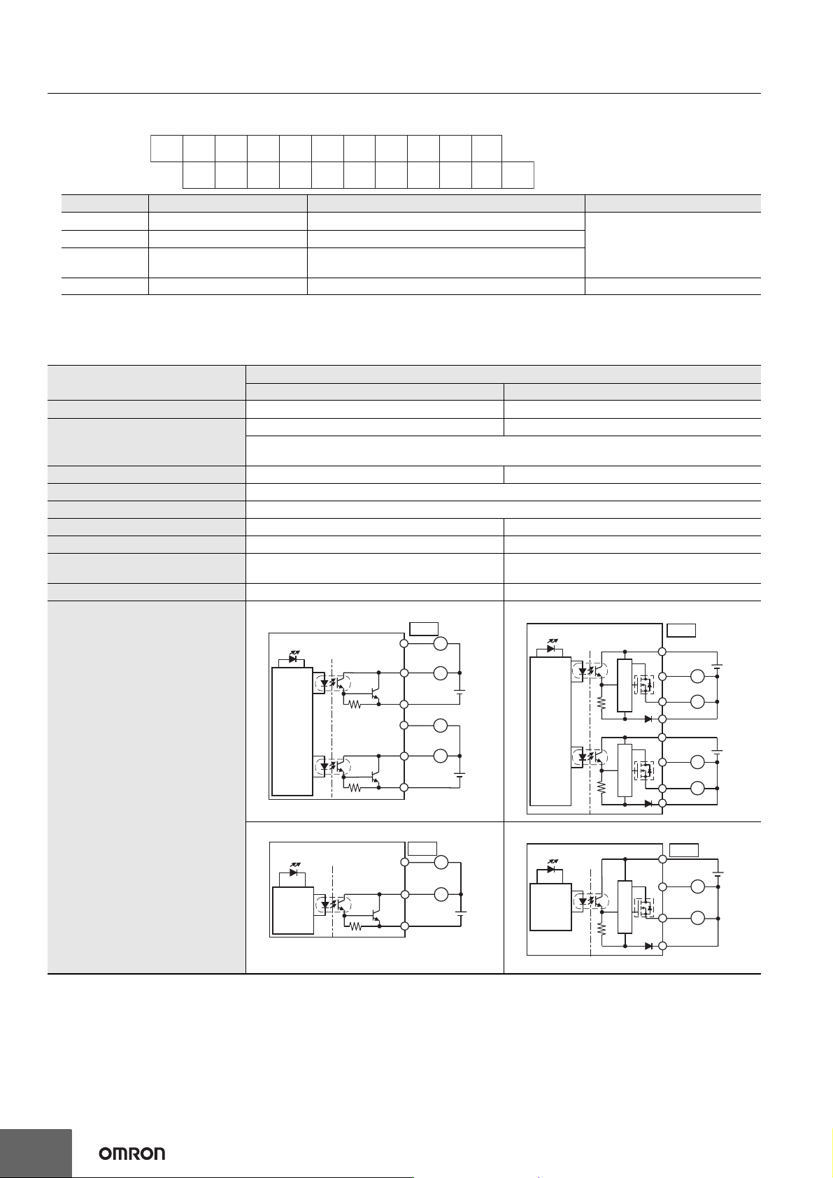
Output Specifications
The models of the CPU Units are divided according to the following two output types: the NPN (sinking) type and PNP (sourcing) type.
There is no difference in specifications between the models with different output terminal numbers.
*1. The internally consumed current from I/O power supply. The current flows from the common terminal Cn (+V) to the 0Vn terminal. The current
consumption of any external load is excluded.
*2. The load short-circuit protection is provided for each point of the PNP (sourcing) type output terminal. It protects the output circuits when a load
short circuit occurs.
Symbol Terminal name Description Reference
C0 (+V) Common terminal Connected to the 24-V side of the I/O power supply.
Refer to the Output Specifications
page.
0V0 0 V terminal Supplies 0 V for the internal circuits for driving.
00 to 09 Output terminals
PNP (sourcing) type output with the load short-circuit
protection function
NC NC Do not connect anything. ---
Item
Specification
NX1P2-DT NX1P2-DT1
Internal I/O common NPN (sinking) PNP (sourcing)
Maximum switching capacity
12 to 24 VDC (10.2 to 28.8 VDC), 300 mA per point 24 VDC (15 to 28.8 VDC), 300 mA per point
NX1P2-1
40DT: 1.8 A/common (3.6 A/Unit)
NX1P2-9024DT
: 2.4 A/common (2.4 A/Unit)
Minimum switching capacity 12 to 24 VDC (10.2 to 28.8 VDC), 1 mA 24 VDC (15 to 28.8 VDC), 1 mA
Leakage current 0.1 mA max.
Residual voltage 1.5 V max.
ON response time 0.1 ms max. 0.5 ms max.
OFF response time 0.8 ms max. 1.0 ms max.
Current consumption from I/O
power supply *1
---
NX1P2-140DT1: 40 mA/common
NX1P2-9024DT1: 50 mA/common
Load short-circuit protection Not provided Provided *2
Circuit configuration
NX1P2-1
40DT
NX1P2-1
40DT1
NX1P2-9024DT NX1P2-9024DT1
NC
NC
NC
NC
NC
NC
NC
NC08
NC09
06
07
04
05
02
03
00
010V0
NC
C0
(+V)
Output indicator
08
07
L
L
Internal
circuits
10.2 to 28.8 VDC10.2 to 28.8 VDC
C1 (0V)
C0 (0V)
15
00
L
L
OUT
. . .
. . .
. . .
. . .
Output indicator
L
Internal
circuits
08
15
L
L
L
15 to 28.8 VDC
C1 (+V)
0V1
C0 (+V)
15 to 28.8 VDC
07
00
0V0
OUT
Short-circuit
protection
Short-circuit
protection
. . .
. . .
. . .
. . .
Output indicator
L
Internal
circuits
10.2 to 28.8 VDC
09
00
C0 (0V)
L
OUT
. . .
. . .
Output indicator
Internal
circuits
Short-circuit
protection
15 to 28.8 VDC
C0 (+V)
L
L
09
00
0V0
OUT
. . .
. . .
Machine Automation Controller NX1P
29
Part Names and Functions
CPU Unit
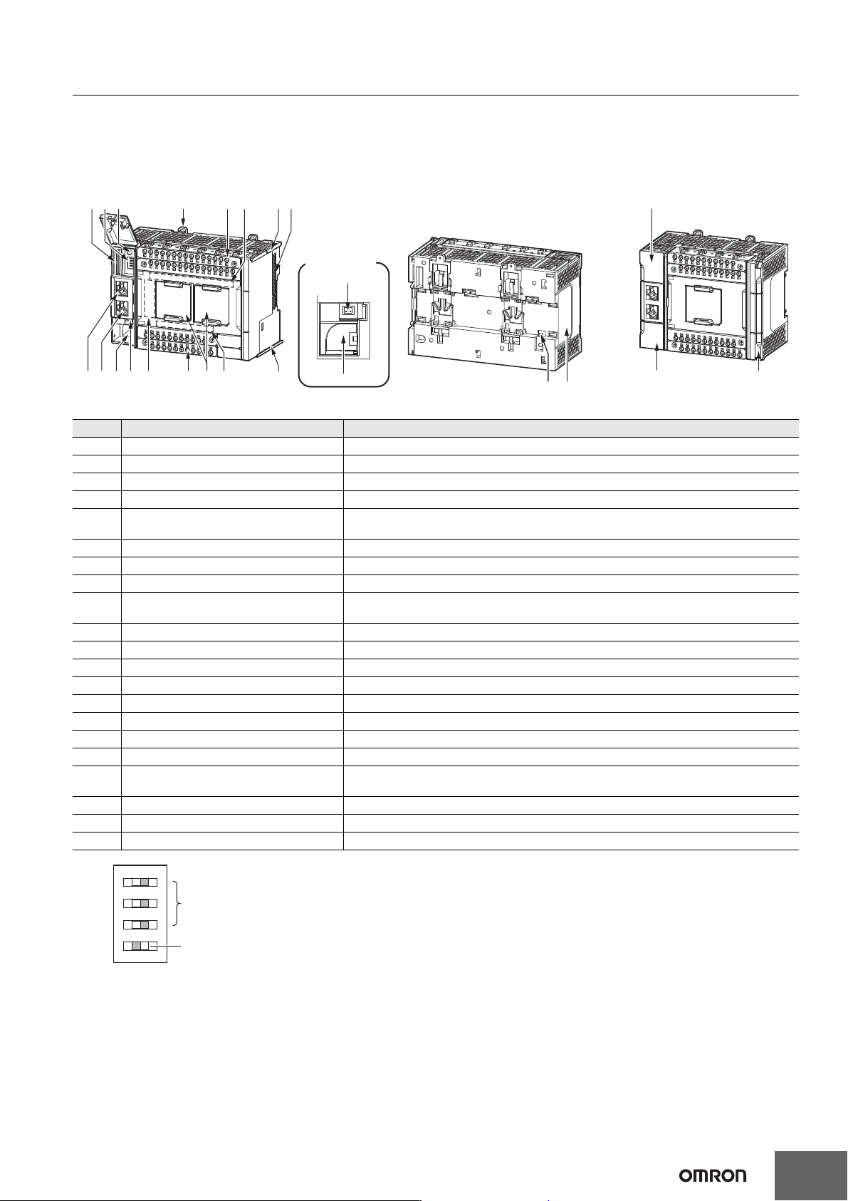
The following two models have the different numbers of the option board slots and built-in I/O points, but the names and functions of their parts
are the same. Refer to the Ordering Information page for the CPU Unit models and specifications such as the number of built-in I/O points.
*1. To use Safe Mode, set the DIP switch as shown below and then turn ON the power supply to the Controller.
If the power supply to the Controller is turned ON with the CPU Unit in Safe Mode, the CPU Unit will start in PROGRAM mode. Use the Safe
Mode if you do not want to execute the user program when the power supply is turned ON or if it is difficult to connect the Sysmac Studio.
For information on Safe Mode, refer to the NJ/NX-series Troubleshooting Manual (Cat. No. W503).
*2. Refer to the NJ/NX-series CPU Unit Software User’s Manual (Cat. No. W501) for details on backing up data.
Letter Name Function
A SD Memory Card connector Connects the SD Memory Card to the CPU Unit.
B DIP switch Used in Safe Mode *1 or when backing up data *2. Normally, turn OFF all of the pins.
C SD Memory Card power supply switch Turns OFF the power supply so that you can remove the SD Memory Card.
D DIN Track mounting hook These hooks are used to mount the Unit to a DIN Track.
E Input terminal block
This terminal block is used for wiring for the Unit power supply, grounding, and built-in
input.
F Input indicator Shows the operation status of the built-in input.
G Unit hookup guides These guides are used to mount an NX Unit or End Cover.
H NX bus connector This connector is used to connect the CPU Unit to the NX Unit on the right of the CPU Unit.
I
Option board slot 1 (left),
Option board slot 2 (right)
Remove the covers of the slots and mount Option Boards. For the models with 24 built-in
I/O points, only one slot is provided. Keep the removed covers in a safe place.
J Output indicator Shows the operation status of the built-in output.
K Output terminal block This terminal block is used to wire the built-in output.
L CPU Unit operation status indicator Shows the operation status of the CPU Unit.
M Battery connector Connector to mount the backup battery that is sold separately.
N Battery slot Used to mount the backup battery that is sold separately.
O Built-in EtherCAT port (port 2) Connects the built-in EtherCAT with an Ethernet cable.
P Built-in EtherNet/IP port (port 1) Connects the built-in EtherNet/IP with an Ethernet cable.
Q SD Memory Card cover Cover for the SD Memory Card and DIP switch. The cover swings upward.
R End Cover
Cover to protect the CPU Unit and NX Units.
One End Cover is provided with the CPU Unit.
S Battery cover Cover for the battery slot. Remove this cover when you mount/remove the battery.
T ID information indication Shows the ID information of the CPU Unit.
U DIN Track contact plate This plate is connected internally to the functional ground terminal on the terminal block.
NX1P2-140
NX1P2-9024
(A)(B)(C) (D)
(G)
(G)(J)
(U)
(H)
(I)
(E)
(F)
(Q)
(K)
(R)(S)
(T)
(L)(M)(N)(O)(P)
(M) and (N)
details
(N)
(M)
OFF
ON
O
N
1
2
3
4
Machine Automation Controller NX1P
30
Option Board
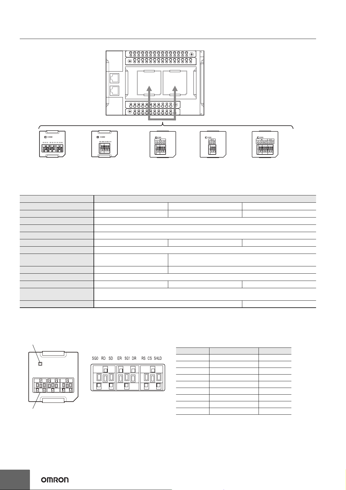
Specifications of Serial Communications Option Board
*1. Projecting parts such as a terminal block is not included. When the Option Board is mounted to the CPU Unit, it protrudes through the CPU
Unit surface. Refer to the NX-series NX1P2 CPU Unit Hardware User’s Manual (Cat. No. W578) for details.
*2. The terminals are isolated from the internal circuits of the CPU Unit.
RS-232C Option Board (NX1W-CIF01)
Item Specification
Model NX1W-CIF01 NX1W-CIF11 NX1W-CIF12
Communications port One RS-232C port One RS-422A/485 port One RS-422A/485 port (isolated)
Communications method Half-duplex
Synchronization method Start-stop synchronization
Baud rate 1.2/2.4/4.8/9.6/19.2/38.4/57.6/115.2 kbps
Transmission distance 15 m 50 m 500 m
Supported protocol Host link, Modbus-RTU master, and no-protocol
Connection type
Screwless clamping terminal block
(9 terminals)
Screwless clamping terminal block (5 terminals)
Applicable wire size AWG28 to 20 AWG24 to 20
Dimensions (mm) *1 35.9 × 35.9 × 13.5 (W×H×D)
Weight 16 g 13 g 14 g
Power consumption
Included in the CPU Unit power consumption.
The Option Board power consumption is included in the definition of the CPU Unit power consumption.
Isolation method No isolation Isolation *2
NX-series NX1P2 CPU Unit
Option Board
(NX1W-CIF01)
RS-232C
Option Board
(NX1W-CIF11/12)
RS-422A/485
Analog Input
Option Board
(NX1W-ADB21)
Analog Output
Option Board
(NX1W-DAB21V)
Analog I/O
Option Board
(NX1W-MAB221)
COMM
Communications status indicator
RS232C terminal block
SG0 RD SDER SG1 DR RS CS SHLD
RS-232C Terminal Block
Abbreviation Signal name I/O
SG0 Signal grounding ---
RD Receive data Input
SD Send data Output
ER Data terminal ready Output
SG1 Signal grounding ---
DR Data set ready Input
RS Send request Output
CS Data can be sent Input
SHLD Shield ---
Note: 1. As the Option Board does not have a 5 V power supply terminal, it cannot be connected to external
converters such as an CJ1W-CIF11 and NT-AL001, or an NV3W-M20L Programmable Terminal.
2. The terminal block is not removable.